Page 3 of 5
Posted: Thu Feb 16, 2012 2:17 pm
by heathicus
dusty wrote:You added casters to the drawings (neat and a subject for another thread) but you did not alter any of the other vertical dimensions. That doesn't feel like it will work out in the long run. In the end - the height off the floor must be the same for the outfeed table top and the top of the cabinet saw bed.
Actually, I had already accounted for them in the first drawings. The bottom of the cabinets was already 4" off of the "floor" to make room for the casters. They just weren't in the drawing. So this time I added the casters and extended the back legs down to the floor. Since everything was "floating", adding the casters didn't change the table heights.
JPG and pennview:
I'm trying to follow what you said. I had to sketch something out in MSPaint real quick to see if I understood it... is this what you mean?
[ATTACH]16276[/ATTACH]
The blue board would be the leg. The dark red the front rail. The brown the side rail. The yellow is the path of the lag bolts.
Posted: Thu Feb 16, 2012 2:42 pm
by pennview
Yes, that works. I use dry wall type screws (coarse threads) for just about everything these days, but lag bolts work too. It's just a matter of what you have available.
My thought was to screw the two side pieces together, then adding the front piece by screwing it to the side pieces with a couple of screws running from front to back. That way you have screws running in two directions. But, here again, it probably doesn't make much difference.
40 yr old joint
Posted: Thu Feb 16, 2012 3:12 pm
by JPG
heathicus wrote:Actually, I had already accounted for them in the first drawings. The bottom of the cabinets was already 4" off of the "floor" to make room for the casters. They just weren't in the drawing. So this time I added the casters and extended the back legs down to the floor. Since everything was "floating", adding the casters didn't change the table heights.
JPG and pennview:
I'm trying to follow what you said. I had to sketch something out in MSPaint real quick to see if I understood it... is this what you mean?
[ATTACH]16276[/ATTACH]
The blue board would be the leg. The dark red the front rail. The brown the side rail. The yellow is the path of the lag bolts.
Close. but the brown goes all the way to the front of the leg, and 'maroon' goes half way across the front of the leg to the side rail inside surface. Two bolts from the side 3/4" in from the front end, through the leg, and into the center of the front rail.
I have done it differently with square legs that is stronger, but more complicated.
The leg is doubled 2x4.
[ATTACH]16277[/ATTACH]
The rails rest on 1/2" deep shoulders. The silver colored bolts are lag bolts into the 2x4 rails. The black bolts are threaded bolts through the leg with nuts on the back of the leg. The end grain shown is 1" since the laping is also done vertically.
Ignore the irish lace!:rolleyes:
Posted: Thu Feb 16, 2012 5:54 pm
by heathicus
More like this?
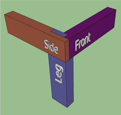
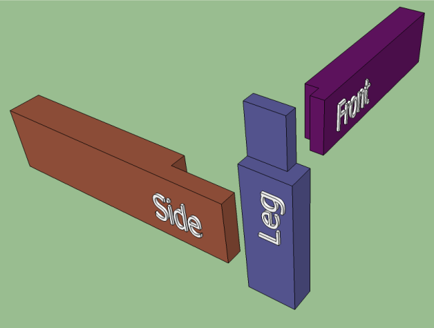
Four lag bolts going into the side - two into the end of the front rail, 2 into the leg.
Posted: Thu Feb 16, 2012 5:59 pm
by dusty
You said something about building with with construction grade lumber (2x4s). If you are going to do this, consider passing the 2x4s through a planer to size them all the same. The finished product won't be any stronger but it will be purdier.
Posted: Thu Feb 16, 2012 7:52 pm
by JPG
heathicus wrote:More like this?
Four lag bolts going into the side - two into the end of the front rail, 2 into the leg.
That is my original suggestion with 2 more bolts. Not sure half lap is best. - maybe 1/3 lap?;) 2 lag and two machine bolts. All pass all the way through the leg. 2 lag into front rail, two into nuts/washers.
Posted: Thu Feb 16, 2012 9:58 pm
by beeg
pennview wrote:I use dry wall type screws (coarse threads) for just about everything these days, but lag bolts work too.
You know those screws are brittle and snap off pretty easily?
Posted: Thu Feb 16, 2012 10:19 pm
by heathicus
beeg wrote:You know those screws are brittle and snap off pretty easily?
I've never had one break, but every time I use one, I hear Mike Holmes chastising me. "You don't use
drywall screws in
wood!" I just hope he never inspects my shop!
Posted: Fri Feb 17, 2012 8:12 am
by pennview
I understand that dry wall screws are brittle, but I've never had a dry wall screw break and I use them on most everything, and I predrill the pilot holes so there is no stress on the screw when assembling things. One exception for sure would be hanging kitchen cabinets on the wall or some similar use.
Typically though, glue is what holds my assemblies together and the screws are more or less merely the clamps that hold the parts together until the glue sets up.
Posted: Fri Feb 17, 2012 8:16 am
by pennview
Regarding the outfeed table project, were I building it I'd change the corner joint a bit. I'd run the front rail the full width of the out feed table by notching the leg AND the side rail. That gives you more surface to attach the components together and in my view give you a somewhat stonger assembly because you can add more screws or lag bolts.