Page 5 of 6
Posted: Wed Dec 12, 2012 2:58 pm
by skou
There is an adapter to retro-fit the E model ripfence to the ER type. It looks kind of hump-backed, bolts into those holes, and has a hole to put the mortise hold-down into, as well as the back clamp.
Oh, the mortise hold down hole, will also hold the dead center from the tailstock, so you can cut round things with the jigsaw. (53 PTWFE.)
steve
Posted: Wed Dec 12, 2012 3:02 pm
by skou
It sounds like you may have your table on backwards. The steel bar, should be on the front of the table, not the back. (You called the mount on the E model fence, as mounting on the back That channel should be on the front.)
Just lift off the table from the carriage, and turn it around.
steve
Posted: Mon Dec 17, 2012 5:14 pm
by dgale
heathicus wrote:
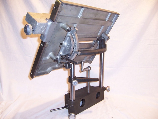
I see something else that says ER. The table raiser arm. I don't think the 10E had that. I see the hole in the carriage for the raiser crank (not sure if the 10E had that threaded hole or not), but, I don't see the crank itself.
I did end up finding the "raiser crank" in the work bench drawer. I understand that it screw into the hole in the carriage but otherwise I don't really understand how the raiser arm and raiser crank are used to raise the table up and down (?) Do you screw the crank in/out to the desired height and then lower the table until the raiser arm rests on top of the crank? I can't see how else they would work in unison to set the table height.
Posted: Tue Dec 18, 2012 3:29 pm
by JPG
dgale wrote:I did end up finding the "raiser crank" in the work bench drawer. I understand that it screw into the hole in the carriage but otherwise I don't really understand how the raiser arm and raiser crank are used to raise the table up and down (?) Do you screw the crank in/out to the desired height and then lower the table until the raiser arm rests on top of the crank? I can't see how else they would work in unison to set the table height.
Position the arm on the crank end. Tighten the arm. Loosen the table post clamps. Rotate the clamp. The arm and table should rise and fall together.
Posted: Tue Dec 18, 2012 3:45 pm
by heathicus
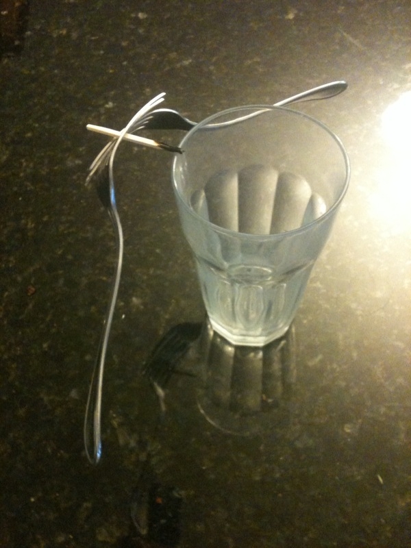
One might look at the arrangement and think it would cock the table sideways. But it doesn't because the table's center of balance is (roughly) at the end of that raiser arm. Much in the same way this "magic trick" works to balance two forks on the edge of a glass using a match.
Posted: Tue Dec 18, 2012 5:37 pm
by JPG
heathicus wrote:One might look at the arrangement and think it would cock the table sideways. But it doesn't because the table's center of balance is (roughly) at the end of that raiser arm. Much in the same way this "magic trick" works to balance two forks on the edge of a glass using a match.
My My! The things one can learn here!

Maybe we need a parlor tricks forum!:D
Posted: Tue Dec 18, 2012 6:27 pm
by robinson46176
As I recall from my days on Skip's 10-ER Yahoo list you want to exercise caution with those table lifters...

Sometimes when the table post are not kept sliding freely (or someone forgets to loosen the table lock knobs) and they try to force the table lifter crank the lifter breaks (it is cast iron). There were some on the list that had made replacement lifters that clamped on both table post instead of one. I think the new double ended ones they made were made of aluminum.
.
Posted: Tue Dec 18, 2012 10:26 pm
by dgale
JPG40504 wrote:Position the arm on the crank end. Tighten the arm. Loosen the table post clamps. Rotate the clamp. The arm and table should rise and fall together.
Sorry...I'm feeling a bit dense tonight. I think I understand how this works but am not sure about how exactly to "Position the arm on the crank end" and still be able to rotate the crank to raise/lower to the desired height. Any chance someone can post a photo of how the arm sits on the crank when it's positioned properly?
Posted: Wed Dec 19, 2012 1:55 am
by JPG
dgale wrote:Sorry...I'm feeling a bit dense tonight. I think I understand how this works but am not sure about how exactly to "Position the arm on the crank end" and still be able to rotate the crank to raise/lower to the desired height. Any chance someone can post a photo of how the arm sits on the crank when it's positioned properly?
The arm has a 'dimple' on the bottom near the end.
The crank has a half spherical or tapered end.
The crank end goes into the dimple.
This allows the arm to stay over the crank shaft as it is turned.
You attach the crank to the carriage from the bottom of the carriage so the crank handle is below the carriage, and the crank shaft end is above the carriage.
Posted: Wed Dec 19, 2012 9:39 am
by dgale
JPG40504 wrote:The arm has a 'dimple' on the bottom near the end.
The crank has a half spherical or tapered end.
The crank end goes into the dimple.
This allows the arm to stay over the crank shaft as it is turned.
You attach the crank to the carriage from the bottom of the carriage so the crank handle is below the carriage, and the crank shaft end is above the carriage.
Okay, I got it now...I envisioned the crank the other way around and hence why I couldn't visualize how the arm sat on the crank. Thanks for the explanation. What messed me up was I found this photo, which shows the crank installed the other way around: