Updating Currently In Progress...the guide is accurate but I am changing it to make it easier to read.
The thread will cover replacing bearings, rewiring to be reversible, and rewiring for 115v or 230v. The motor example used is an AO Smith 1 & 1/8th Horsepower motor, but the process is similar for the 3/4 HP and GE motors as well. Links to tools or products are simply what I use and am happy with, but not necessarily linked to where I bought them.
Your safety is your responsibility! If you are not confident that you are able to complete this entire process safely, please consult a motor shop or one of the forum members who offers this service.
Clicking any image will open a larger photo gallery in a new window. When referring directly to a picture, (parenthesis and italics will be used). When referring to wire colors, colored font will be used, e.g. red, white, black, etc.
Tools Needed For Bearing Replacement / Rebuild:
Bearing Puller or Press
Good Snap Ring Pliers
Needle Nose Pliers
5/32" Allen Wrench
#2 and #3 Phillips Head Screw Drivers
Flat Head Screwdriver
1/4" Socket
1" x 4" x 30" board
Marker / Sharpie
Additional Tools Needed For Re-wiring / Reversing:
Ohmmeter / Voltmeter
Soldering Iron and Solder
Wire Stripper and Cutter
Sharp Knife, Razor, X-Acto Blade, etc.
Parts List:
NTN 6203LLBC3 Electric Motor Bearings or Equivalent (17mm x 40mm x 12mm)
Insulating Spray Varnish
Forward / Reverse Switch (DPDT On/On Rated for Machine Tools)
If you are replacing bearings and not re-wiring / reversing your motor, follow through post # 6
If you are reversing your motor, I strongly recommend replacing the wiring with 12 gauge wiring. This will allow the motor to take full advantage of a 15 or 20 amp power source. The best forward/reverse switch would be a DPDT On/On, but a DPDT On/Off/On switch could be used also. If an On/Off/On is used and the motor is started with the switch in the center position, the motor will hum but not spin. If the operator allows the motor to stay on like this for too long, it will burn up.
If upgrading to a 20 amp circuit, everything in that circuit should be rated for 20 amps. This includes the wall outlet and wiring, power cord, On/Off switch, Forward/Reverse switch, and wiring. I found the wiring for less than $5, the switches for $8.50 each, and the new power cord is just as cheap. The switches I purchased specifically said for machine tools up to 1.5 horsepower.
AO Smith 1 & 1/8 HP Motor Guide - Forward / Reverse, Bearings, Wiring, etc.
Moderators: HopefulSSer, admin
-
joshh

- Platinum Member
- Posts: 723
- Joined: Tue Jan 08, 2013 8:53 pm
- Location: Dallas / Fort Worth, Texas
Shopsmith Motor Guide - Bearings, Wiring, Reversing, Dual Voltage 115v/230v
- 1986 Mark V 500 Mini
- 1985 Mark V 510 with reversible motor, bandsaw, jointer, and double-tilt.
I offer quality motor reversal, rebuilding, and rewiring. Contact me at HarbourTools@live.com
- 1985 Mark V 510 with reversible motor, bandsaw, jointer, and double-tilt.
I offer quality motor reversal, rebuilding, and rewiring. Contact me at HarbourTools@live.com
-
joshh
- Platinum Member
- Posts: 723
- Joined: Tue Jan 08, 2013 8:53 pm
- Location: Dallas / Fort Worth, Texas
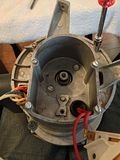
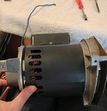
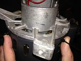
Remove Motor From Headstock:
- Turn the ShopSmith on and set the speed to high.
- Turn off and unplug the machine.
- Lift the ShopSmith into drill-press mode.
- Install the main table into the carriage BACKWARDS (inserted into the bottom). This provides a shelf to rest the motor pan & motor when unscrewed from the headstock.
- Remove the belt cover.
- Slip the motor belt off the motor pulley.
- Disconnect the motor wires from the ON/OFF switch.
- Use a #2 Phillips head screwdriver to remove the 5 screws holding the motor pan to the headstock (marked by arrows below).
- Rest the motor pan & motor on the reversed main table.
- Use a 1/4" socket to remove the screw holding the ground wire to the motor.
- Use a #3 Phillips Head screwdriver to remove the 4 screws holding the motor to the motor pan.


-
joshh
- Platinum Member
- Posts: 723
- Joined: Tue Jan 08, 2013 8:53 pm
- Location: Dallas / Fort Worth, Texas
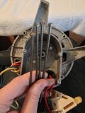
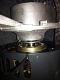
Remove Motor Sheaves / Pulley:
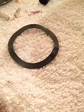
- Compress the spring and remove the retaining ring. The retaining ring is inverted (see 3rd image) and may be difficult to replace if lost. If you can't compress & hold the spring by hand, follow the next step.
- OPTIONAL: Take a 1" x 4" x 24" board and drill a small pilot hole through the center of the face. Counterbore a 1.5" diameter hole about 1/8" deep. Flip the board over and drill a 3/4" diameter all the way through. The large washer on the top of the motor spring will slip inside the counterbore.
- Release and remove the spring with washer.


- Remove the floating sheave.
- Use a 5/32" allen wrench to remove the set screw at the base of the keyway.
- Remove the key and fan sheave.


-
joshh
- Platinum Member
- Posts: 723
- Joined: Tue Jan 08, 2013 8:53 pm
- Location: Dallas / Fort Worth, Texas
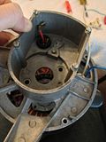
Remove Centrifugal Start Switch:
- Mark the position of the front & rear end caps to the center housing. This is important during re-assembly or the mounting feet will not line up with the motor pan.
- Loosen the 4 screws and remove the cover over the centrifugal switch
- Use a 1/4" socket to remove the screw holding the centrifugal switch and unplug the wires.


- Use a good pair of needle nose pliers or forceps to remove the springs on the centrifugal weight mechanism.
- The two halves of the weight mechanism are held together by a tight fit. The ears on the upper half fit into the holes of the lower half. Unhook the upper half and remove.
- Remove the screw holding the lower half to the motor shaft.


-
joshh
- Platinum Member
- Posts: 723
- Joined: Tue Jan 08, 2013 8:53 pm
- Location: Dallas / Fort Worth, Texas
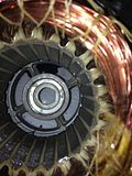
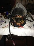
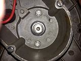
Remove End Caps And Rotor Assembly:
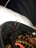
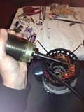
Point the motor towards the floor with the rear facing up. I found holding it between my legs worked very well for these next steps. Use a 1/4" socket to remove the 4 bolts that hold the front and rear end caps to each other. Next, remove the 2 bolts holding the rotor assembly to the rear end cap.
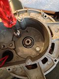
It is not necessary to move or remove the front end cap. Separate the rear end cap from the motor housing. As you remove the rear end cap, feed the red centrifugal switch wires through the grommet and take care not to pull on them as you may damage where they attach to the windings. The rotor may be stuck to the rear end cap. If so, hold onto the motor shaft on the front while removing the rear end cap. After the rear end cap is removed, gently remove the rotor assembly from the housing.
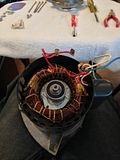


It is not necessary to move or remove the front end cap. Separate the rear end cap from the motor housing. As you remove the rear end cap, feed the red centrifugal switch wires through the grommet and take care not to pull on them as you may damage where they attach to the windings. The rotor may be stuck to the rear end cap. If so, hold onto the motor shaft on the front while removing the rear end cap. After the rear end cap is removed, gently remove the rotor assembly from the housing.


-
joshh
- Platinum Member
- Posts: 723
- Joined: Tue Jan 08, 2013 8:53 pm
- Location: Dallas / Fort Worth, Texas
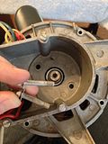
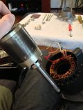
Replace Bearings:
The bearings can be replaced at this point. I used NTN 6203LLB sealed bearings.
If you are only replacing the bearings and not reversing your motor, re-install the rotor assembly (with new bearings) into the housing. There is a curved washer that sits between the front bearing and the front end cap.
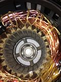
This concludes the bearing replacement tutorial. Follow the previous instructions backwards for re-assembly. Continue on for instructions on re-wiring or reversing the motor.
If you are only replacing the bearings and not reversing your motor, re-install the rotor assembly (with new bearings) into the housing. There is a curved washer that sits between the front bearing and the front end cap.


This concludes the bearing replacement tutorial. Follow the previous instructions backwards for re-assembly. Continue on for instructions on re-wiring or reversing the motor.
-
joshh
- Platinum Member
- Posts: 723
- Joined: Tue Jan 08, 2013 8:53 pm
- Location: Dallas / Fort Worth, Texas
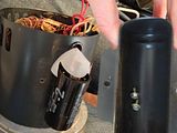
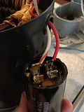
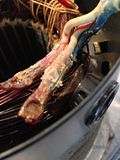
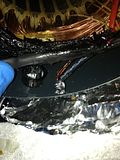
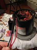
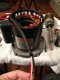
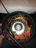
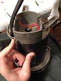
Use a 1/4" socket to remove the 2 screws holding the capacitor housing to the motor. Mark the red wire and the terminal on the capacitor with a permanent marker (per JPG40504, this step is unnecessary as the capacitor is not polarized). Unplug and remove the capacitor. *(The last picture shows the circuit with switch and capacitor attached. This is informational only and not a step in the process*)
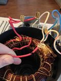
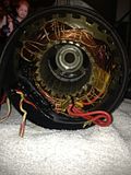
The windings are bundled and tied with string from the factory. This string may be deteriorated to the point that it falls off with any manipulation. JPG40504 recommended re-bundling the windings with cable ties after rewiring is complete. Of course, care must be taken to ensure nothing interferes with moving parts.
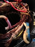
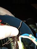
Use a small zip tie to hold the red wires from the centrifugal switch out of the way. The "negative" or neutral white wire is spliced with the neutral side of the start circuit (left splice in the images below). This is our first target. Begin dissecting the splice with an x-acto blade, razor, scalpel, etc. Take care not to nick or cut any of the other bare wires in the windings. They are coated with a non-conductive, protective varnish. You will find 3 solid, bare wires connected to the stranded white wire. If you are upgrading the motor wiring to 12 gauge, cut the bare wires as close to the crimped connector as possible. If you are not upgrading the wiring, you will need to cut only the single bare start wire (you may also ignore future steps relating to replacing the wires). The start wire is smaller than the 2 run wires. You can confirm this is the correct wire with an OHM meter. The resistance between the bare start wire and one of the red wires to the centrifugal switch should read between 6 - 8 OHM's of resistance (thank you Bill Mayo for this info). Take a sharp knife or razor and scrape the varnish off the bare wires. Do not manipulate the bare wires any more than necessary, as you may rub the varnish off somewhere unseen and create a short. The ends of the bare wires must be clean and free of any dirt or varnish.


The windings are bundled and tied with string from the factory. This string may be deteriorated to the point that it falls off with any manipulation. JPG40504 recommended re-bundling the windings with cable ties after rewiring is complete. Of course, care must be taken to ensure nothing interferes with moving parts.
Use a small zip tie to hold the red wires from the centrifugal switch out of the way. The "negative" or neutral white wire is spliced with the neutral side of the start circuit (left splice in the images below). This is our first target. Begin dissecting the splice with an x-acto blade, razor, scalpel, etc. Take care not to nick or cut any of the other bare wires in the windings. They are coated with a non-conductive, protective varnish. You will find 3 solid, bare wires connected to the stranded white wire. If you are upgrading the motor wiring to 12 gauge, cut the bare wires as close to the crimped connector as possible. If you are not upgrading the wiring, you will need to cut only the single bare start wire (you may also ignore future steps relating to replacing the wires). The start wire is smaller than the 2 run wires. You can confirm this is the correct wire with an OHM meter. The resistance between the bare start wire and one of the red wires to the centrifugal switch should read between 6 - 8 OHM's of resistance (thank you Bill Mayo for this info). Take a sharp knife or razor and scrape the varnish off the bare wires. Do not manipulate the bare wires any more than necessary, as you may rub the varnish off somewhere unseen and create a short. The ends of the bare wires must be clean and free of any dirt or varnish.


-
joshh
- Platinum Member
- Posts: 723
- Joined: Tue Jan 08, 2013 8:53 pm
- Location: Dallas / Fort Worth, Texas
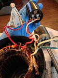
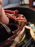
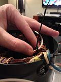
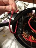
Connect a 3 foot length of red, 16 gauge stranded wire to the bare start wire. If you choose to crimp, make sure the connector is similar to the original one and rated for VAC. I chose to solder the connection after braiding the new stranded wire around the bare start wire. Connect a 3 foot length of white, 12 gauge stranded wire to the two remaining bare run wires. Cover the connections with heat-shrink tubing (I used red tubing for this first layer and black for the next to aid in photography). Slide heat-shrink down the unattached ends of the white and red wires (with both wires bundled together) as far as it will go (2nd picture). Next, slide heat-shrink over the connections from the opposite end. This provides stability and double-insulation to the soldered wires. I painted the top of the windings underneath the new connections with liquid electrical tape in case I nicked anything or rubbed the varnish off. Bill Mayo told me that he used liquid tape before he found a spray varnish that he now uses. The varnish is a better solution if available. The liquid electrical tape will harden quicker if you blow on it after application.
(The 1st picture shows the start wires grouped with the new white wire, I had not yet braided or soldered it yet. The last picture shows the splice heat-shrinked, and with the remaining splice dissected as described in the next step)
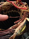
If you are not upgrading to 12 gauge wiring, do not dissect the splice connecting the blue wire and white/red wire. Instead, cut the white/red wire off near the splice and insulate it properly (This is a "HOT" wire when in operation). It will not be connected to anything other than the splice it's part of. Skip to the next post.
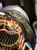
If you are upgrading the wiring to 12 gauge, dissect the splice connecting the blue wire and white/red wire. Seperate, cut, and scrape / clean the bare wires as before. The white/red wire is no longer used, do not reconnect it. Connect a 3 foot length of black, 12 gauge stranded wire to the 2 bare run wires (you can use blue if you wish to match the original, but I used black to match corresponding wire on the power cord) Crimp or solder the connection and heat-shrink. Bundle your new red, white, and black wires together and slide a long piece of heat-shrink over them. Add heat to the bundle while making sure the 3 wires stay flat vs round in the tubing. The exit for the wires through the end cap is directly above the splices. This was not a problem with 16 gauge wire as it is much more flexible. To not stress the windings, route the bundle around the outer rim of the motor housing a full circle (picture 4 and 5) and zip-tie in place so it lies flat against the housing.
(The 1st picture shows the start wires grouped with the new white wire, I had not yet braided or soldered it yet. The last picture shows the splice heat-shrinked, and with the remaining splice dissected as described in the next step)


If you are not upgrading to 12 gauge wiring, do not dissect the splice connecting the blue wire and white/red wire. Instead, cut the white/red wire off near the splice and insulate it properly (This is a "HOT" wire when in operation). It will not be connected to anything other than the splice it's part of. Skip to the next post.
If you are upgrading the wiring to 12 gauge, dissect the splice connecting the blue wire and white/red wire. Seperate, cut, and scrape / clean the bare wires as before. The white/red wire is no longer used, do not reconnect it. Connect a 3 foot length of black, 12 gauge stranded wire to the 2 bare run wires (you can use blue if you wish to match the original, but I used black to match corresponding wire on the power cord) Crimp or solder the connection and heat-shrink. Bundle your new red, white, and black wires together and slide a long piece of heat-shrink over them. Add heat to the bundle while making sure the 3 wires stay flat vs round in the tubing. The exit for the wires through the end cap is directly above the splices. This was not a problem with 16 gauge wire as it is much more flexible. To not stress the windings, route the bundle around the outer rim of the motor housing a full circle (picture 4 and 5) and zip-tie in place so it lies flat against the housing.


-
joshh
- Platinum Member
- Posts: 723
- Joined: Tue Jan 08, 2013 8:53 pm
- Location: Dallas / Fort Worth, Texas
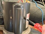
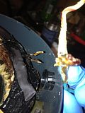
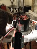
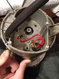
Mark black stripes around a 2 foot length of red, 16 gauge stranded wire. Route this red/black wire through the grommet where the capacitor is housed and connect it to the capacitor. Connect the red capacitor wire (2nd and 3rd pictures below, shown in post #7 and repeated for clarity) to the capacitor. Ensure the connections to the capacitor are tight, and re-install the capacitor and it's housing (my certified electrician shown in picture 5 checking my connections). The inside of the capacitor housing on my motor had several places where it was bare metal. Since I tend to needlessly over-engineer everything, I smothered the inside with liquid tape. If you choose to do this, keep the coat thin or the capacitor may not fit back in the housing. In hindsight, I'm fairly certain this was point-less and the factory plastic divider is enough to protect the capacitor terminals from contact with the housing. =)
Loop roughly 3" of extra red/black wire then bundle the wire with the previous 3-wire bundle (red, white, and black wires). This will provide a little slack for the capacitor wires and keep stress off the connections. Time to begin re-assembling the motor. Re-install the rotor assembly (hopefully with new bearings). There is a curved washer that goes between the front end cap and the rotor assembly (previously described in the bearing section).


Loop roughly 3" of extra red/black wire then bundle the wire with the previous 3-wire bundle (red, white, and black wires). This will provide a little slack for the capacitor wires and keep stress off the connections. Time to begin re-assembling the motor. Re-install the rotor assembly (hopefully with new bearings). There is a curved washer that goes between the front end cap and the rotor assembly (previously described in the bearing section).


-
joshh
- Platinum Member
- Posts: 723
- Joined: Tue Jan 08, 2013 8:53 pm
- Location: Dallas / Fort Worth, Texas
With the rotor assembly set into the housing, begin routing the wiring through the rear end cap. The 4 wire bundle (red, red/black, white, black) passes through the hole in the end cap near the ground wire screw. The red centrifugal switch wires pass through the grommet as before. Roughly align the marks you made on the housing and the end caps in post #4. The rotor assembly screws go into a plate that moves around a lot...it is easier to start the screws before you seat the rear end cap as shown in picture 3.
Align the reference marks and seat the rear end cap. The cap will not seat completely until the previously installed zip-ties are removed. Remove the zip-ties and fully seat the end caps and housing. Tighten the rotor assembly screws.


Align the reference marks and seat the rear end cap. The cap will not seat completely until the previously installed zip-ties are removed. Remove the zip-ties and fully seat the end caps and housing. Tighten the rotor assembly screws.

