Pro Planer speed control box problem
Moderators: HopefulSSer, admin
-
mountainbreeze

- Platinum Member
- Posts: 508
- Joined: Sun Jan 30, 2011 9:58 pm
- Location: Taylors, South Carolina
Re: Pro Planer speed control box problem
Just for future reference, do you have any part numbers for the triac and diac should they need replacing?
Re: Pro Planer speed control box problem
I am trying to understand. Is the Control Box really nothing more than a variable resistance in series with a DC motor?
-
JPG

- Platinum Member
- Posts: 34632
- Joined: Wed Dec 10, 2008 7:42 pm
- Location: Lexington, Ky (TAMECAT territory)
Re: Pro Planer speed control box problem
TBT, a light dimmer etc. with full wave bridge!BigSky wrote:I am trying to understand. Is the Control Box really nothing more than a variable resistance in series with a DC motor?
╔═══╗
╟JPG ╢
╚═══╝
Goldie(Bought New SN 377425)/4" jointer/6" beltsander/12" planer/stripsander/bandsaw/powerstation /Scroll saw/Jig saw /Craftsman 10" ras/Craftsman 6" thicknessplaner/ Dayton10"tablesaw(restoredfromneighborstrashpile)/ Mark VII restoration in 'progress'/ 10E[/size](SN E3779) restoration in progress, a 510 on the back burner and a growing pile of items to be eventually returned to useful life. - aka Red Grange
-
dj1960gold
- Silver Member
- Posts: 17
- Joined: Wed Mar 26, 2014 11:34 pm
- Location: Denver Colorado
Re: Pro Planer speed control box problem
Longer answer:
No, the control box is not a variable resistor in series with the DC motor.
Technically, its not even a light dimmer in series with a rectifier that is connected to a brush type motor.
Its a triac controller circuit that has extra snubbing added to guarantee proper turn off of the triac every half cycle in the presence of an inductive load. For those of you looking for bedtime reading, the best reference I've found so far is this app note:
http://www.onsemi.com/pub_link/Collateral/AN1048-D.PDF
See figure: 6.13 Phase Controlling a Motor in a Bridge
I don't work with power circuits, its not my specialty. Having stated that disclaimer first, I would repair the control box before using a lamp dimmer and a new rectifier. I would also try harbor freight's router speed controller and a rectifier before using a lamp dimmer.
Yes I know that the lamp dimmer was successfully used earlier in the thread. So that is also an option that appears to work due to the low current draw of the planer feed motor. I would just be sure the lamp dimmer actually controlled the speed properly. Worst case is the triac in the lamp dimmer doesn't turn off every half cycle of the 60Hz, and you get full feed speeds when you don't want it.
I think any triac that has a TO-220 package and a 400 or better Volt rating would work in this circuit. My reasoning is that the feed motor doesn't draw much current as these planers are supposed to work with 15 amp outlets and the planer cutter head motor is almost 15 amps on the standalone models.
Since the circuit was designed in the early 80s, any regular triac (and diac) should be suitable so long as the voltage rating is high enough. An added bonus would be to match the pinout of the existing part on the controller board. These days there are fancy triacs for controlling inductive loads that I don't believe were available in the early 80s (but I could be wrong about that).
This evening I'll take a look at some old Radio Shack Triacs I purchased 20 years ago and also at mouser's catalog and post back later with some links to triac/diacs.
-
dj1960gold
- Silver Member
- Posts: 17
- Joined: Wed Mar 26, 2014 11:34 pm
- Location: Denver Colorado
Re: Pro Planer speed control box problem
Alright, I did some research and made some measurements.
The Bridge Rectifier in my control box is labeled:
GI KBPC04
This is an old part and I think I found a pair of older scans of the data sheet here:
http://www.datasheetarchive.com/dlmain/ ... t53013.pdf
http://www.datasheetarchive.com/dlmain/ ... 121-12.pdf
If that is the correct spec, then the rectifier module is 400V and only 3A. Plus you only get the max 3A if its bolted to a heat sink (which its not in the control box ).
).
This must mean that the feed motor operates under 3A, probably a lot under. I'll try to measure the current during operation once I finish my planer rebuild as I don't think anybody else has done that step yet.
Diac:
(This only applies to my regular planer control board, the PRO Planer circuit doesn't appear to have a diac as shown in photos posted on page 5)
I measured the breakover voltage on my board and saw 35 volts. The diac is a DO-35 package and the closest one on mouser is:
511-DB3GT
http://www.mouser.com/ds/2/389/CD00002289-249612.pdf
Triac:
I was not able to find any data on the triac in the control circuit. My number on the package is different than the one reported on page 5, but I don't think this is a hang up for replacement. We know enough from the other parts to make an educated choice for repair purposes.
I did manage to find the old Radio Shack Triacs from years past in my parts bin. They are 400V, 6A (with heat sink), gate voltage of 3V, and TO-220 package. Pinout is the same, BUT they do not have an isolated tab. The triac on my control board does have an isolated tab. The old RS triacs are unmarked so I'm glad I saved the package with the specs listed
400V and 6A is the minimum numbers for this application in my opinion. We could up the numbers to 600V and 8A and I think it would still work. Its interesting that the planer control triac has an isolated tab, but yet the potentiometer housing is connected to the hot side. There should be thermal conductivity through the TO-220 package, and there is evidence of heat sinking grease that squeezed out when the triac was riveted to the bracket. But I guess the designers thought it still needed more heatsinking, and so they connected the potentiometer housing.
In any case, the closest replacement in the mouser catalog with 400V/6A and a TO-220 package is:
576-Q4006L4
http://www.mouser.com/ds/2/240/E2Triac-18233.pdf
http://www.mouser.com/ProductDetail/Lit ... wZ4DVCM%3d
The pinouts were the same among all of the TO-220 triacs I looked at, so its a drop in replacement.
All of these parts are fairly generic, so shop around and compare with mouser's price. As someone who has purchased small qty of new parts, mouser has been a good experience. But if the surplus guys have it for less, I go with them first.
Lastly, I took a much closer look at the repair photos on page 10 and that lamp dimmer has a rather large inductor on its board. I wonder why that is there as I didn't see any dimmer circuits that showed the need for an inductor. Perhaps it keeps noise out of the mains? Perhaps it also makes the dimmer a good repair for our DC motor control boards
The Radio Shack rectifier used in the prior repair looks like this 8A/400V part:
http://www.radioshack.com/radioshack-8a ... 61181.html
That should work fine.
Next I'm going to try and adjust my planer table to cutter head alignment, I have a small difference across the width that I hope a tooth or two of the sprockets will zero out. Cheers.
The Bridge Rectifier in my control box is labeled:
GI KBPC04
This is an old part and I think I found a pair of older scans of the data sheet here:
http://www.datasheetarchive.com/dlmain/ ... t53013.pdf
http://www.datasheetarchive.com/dlmain/ ... 121-12.pdf
If that is the correct spec, then the rectifier module is 400V and only 3A. Plus you only get the max 3A if its bolted to a heat sink (which its not in the control box
This must mean that the feed motor operates under 3A, probably a lot under. I'll try to measure the current during operation once I finish my planer rebuild as I don't think anybody else has done that step yet.
Diac:
(This only applies to my regular planer control board, the PRO Planer circuit doesn't appear to have a diac as shown in photos posted on page 5)
I measured the breakover voltage on my board and saw 35 volts. The diac is a DO-35 package and the closest one on mouser is:
511-DB3GT
http://www.mouser.com/ds/2/389/CD00002289-249612.pdf
Triac:
I was not able to find any data on the triac in the control circuit. My number on the package is different than the one reported on page 5, but I don't think this is a hang up for replacement. We know enough from the other parts to make an educated choice for repair purposes.
I did manage to find the old Radio Shack Triacs from years past in my parts bin. They are 400V, 6A (with heat sink), gate voltage of 3V, and TO-220 package. Pinout is the same, BUT they do not have an isolated tab. The triac on my control board does have an isolated tab. The old RS triacs are unmarked so I'm glad I saved the package with the specs listed
400V and 6A is the minimum numbers for this application in my opinion. We could up the numbers to 600V and 8A and I think it would still work. Its interesting that the planer control triac has an isolated tab, but yet the potentiometer housing is connected to the hot side. There should be thermal conductivity through the TO-220 package, and there is evidence of heat sinking grease that squeezed out when the triac was riveted to the bracket. But I guess the designers thought it still needed more heatsinking, and so they connected the potentiometer housing.
In any case, the closest replacement in the mouser catalog with 400V/6A and a TO-220 package is:
576-Q4006L4
http://www.mouser.com/ds/2/240/E2Triac-18233.pdf
http://www.mouser.com/ProductDetail/Lit ... wZ4DVCM%3d
The pinouts were the same among all of the TO-220 triacs I looked at, so its a drop in replacement.
All of these parts are fairly generic, so shop around and compare with mouser's price. As someone who has purchased small qty of new parts, mouser has been a good experience. But if the surplus guys have it for less, I go with them first.
Lastly, I took a much closer look at the repair photos on page 10 and that lamp dimmer has a rather large inductor on its board. I wonder why that is there as I didn't see any dimmer circuits that showed the need for an inductor. Perhaps it keeps noise out of the mains? Perhaps it also makes the dimmer a good repair for our DC motor control boards
The Radio Shack rectifier used in the prior repair looks like this 8A/400V part:
http://www.radioshack.com/radioshack-8a ... 61181.html
That should work fine.
Next I'm going to try and adjust my planer table to cutter head alignment, I have a small difference across the width that I hope a tooth or two of the sprockets will zero out. Cheers.
Re: Pro Planer speed control box problem
I did the original repair that started this thread but I know very little about power circuits, controller boards, etc. I started with a busted speed controller and couldn't afford a new one.dj1960gold wrote:
I would just be sure the lamp dimmer actually controlled the speed properly. Worst case is the triac in the lamp dimmer doesn't turn off every half cycle of the 60Hz, and you get full feed speeds when you don't want it.
With a lot of help and suggestions from forum members we came up with the light dimmer solution which fit my budget and capabilities. Since then I have used the planer heavily and it still works just fine. I have run thousands of linear feet through the planer and haven't had a single hiccup.
And by the way, the dimmer DOES control the speed. Does the speed match the original control box exactly? I don't know but the speed range it produces seems appropriate for the planer.
-
rcplaneguy
- Platinum Member
- Posts: 549
- Joined: Mon Sep 23, 2013 6:33 pm
- Location: Chapel Hill, NC
Re: Pro Planer speed control box problem
I guess I'm slow. I leave my pro planer feed speed set at "1", the slowest. Plenty fast for me. Not sure why the occasional user would want or need it to feed faster.
-
dj1960gold
- Silver Member
- Posts: 17
- Joined: Wed Mar 26, 2014 11:34 pm
- Location: Denver Colorado
Re: Pro Planer speed control box problem
tdubnik,tdubnik wrote:
............ Since then I have used the planer heavily and it still works just fine. I have run thousands of linear feet through the planer and haven't had a single hiccup.
Thank you for the update.
Funny, I was thinking about your swap to the HomeDepot dimmer so I went there for lunch today to look at what was on the shelf. I figured I might be able to use the knob and also the potentiometer shaft if they looked compatible. Something to have on hand if my original plan falls through.
So I picked up the cheap one. Its ~$6 now. Here is a schematic drawing:
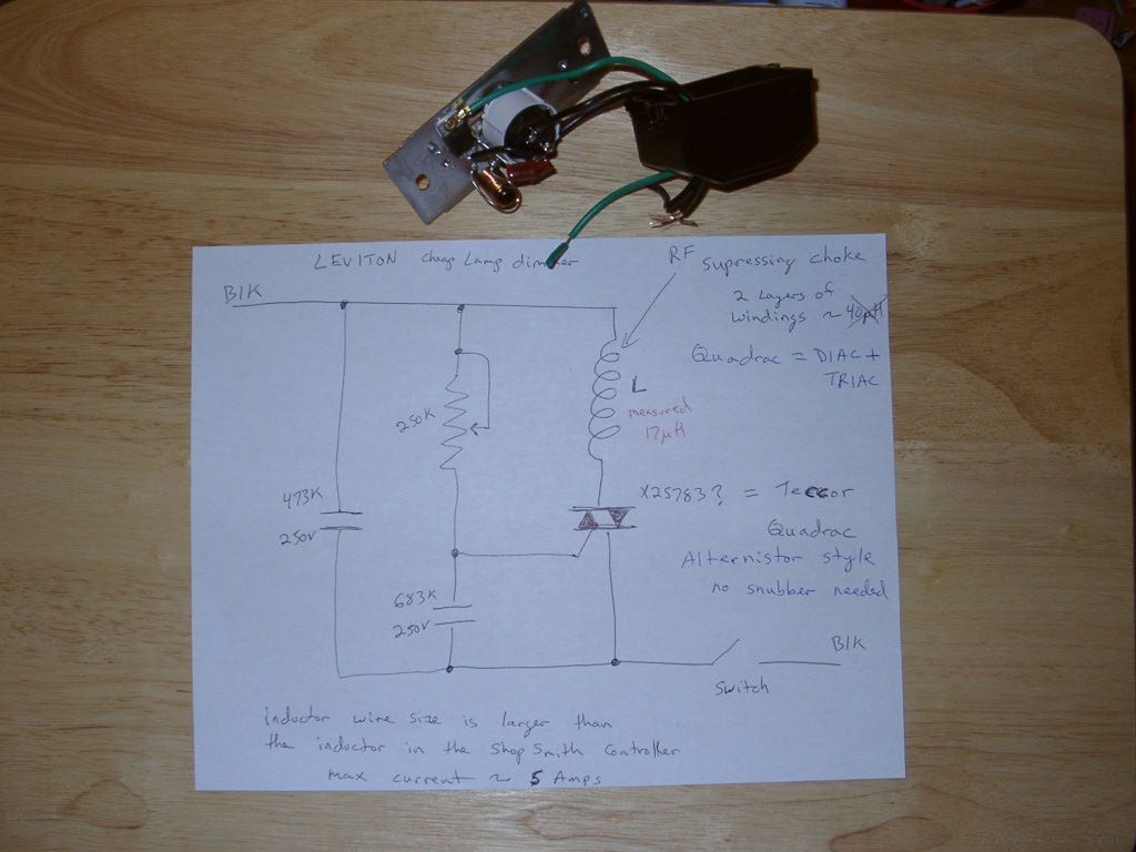
Although the instructions with the dimmer say only to use the device with incandescent light bulbs
After some web research, I think the triac in this dimmer is one of those newer fancy types of triacs called a Quadrac. It has the DIAC built in, and its probably also of the alternistor type. That means that additional snubbing circuitry isn't needed.
Additionally, the dimmer circuit is rated for 600watts, or about 5 amps. I think that is plenty for the feed motor.
I see from your earlier photo on page 10 that you kept the on/off switch. Do you like that and see any reasons the extra feed motor off switch is an advantage?
Regarding feed motor speeds/feed rates, I suspect that the dimmer may have a wider speed range than your original Pro Planer circuit without the DIAC. So perhaps you can attain slower speeds with the dimmer. I'll get my chance to try it out soon enough.
Re: Pro Planer speed control box problem
dj1960gold wrote:tdubnik wrote:
............ Since then I have used the planer heavily and it still works just fine. I have run thousands of linear feet through the planer and haven't had a single hiccup.
I see from your earlier photo on page 10 that you kept the on/off switch. Do you like that and see any reasons the extra feed motor off switch is an advantage?
I never use the additional on/off switch. I just leave it on all the time and use the normal switch.
-
dj1960gold
- Silver Member
- Posts: 17
- Joined: Wed Mar 26, 2014 11:34 pm
- Location: Denver Colorado
Re: Pro Planer speed control box problem
I'm back and I owe everybody an update on my potentiometer shaft repair.
The NOS potentiometer I ordered showed up and I immediately realized it wouldn't work. The shaft is too short. It was the right style of potentiometer, but the shaft was so short it was hardly any longer than the broken original shaft. So I went back to square one.
It finally dawned on me that the Atari 2600 console from the late 70s/early 80s had paddle controllers with similar potentiometers. Lucky me, I had collected a bunch of these from a garage sale last year which I fixed up and gave out as Christmas gifts to the older generation in my family. Among my big box of Atari parts were non-functional paddle controllers, perfect for parts pirating.
Here is a photo of the Atari paddle controller shaft next to the NOS potentiometer I purchased and also next to the broken original:
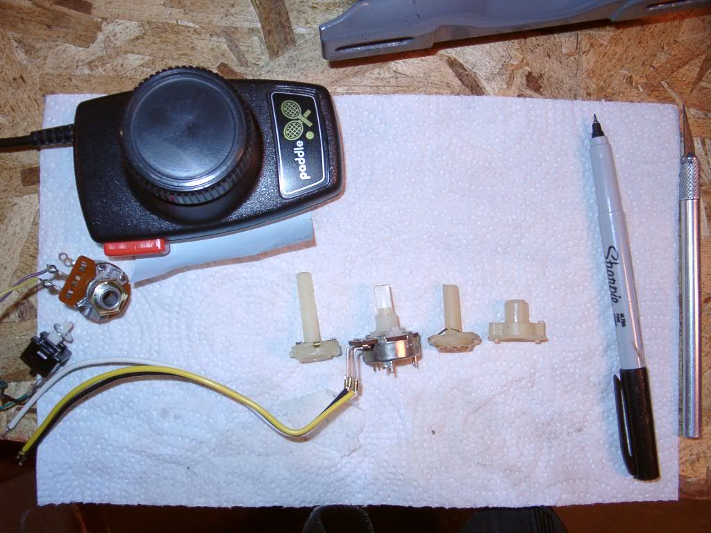
The Atari paddle potentiometer shaft isn't an exact replacement, but its close enough. The one thing I changed/modified is to cut away the limit stop to match the original speed controller adjustment range. The next two photos shows the limit stop differences between the Atari shaft with the original (note: the vice grips are NOT marring the shafts, just holding them so I can take the picture):
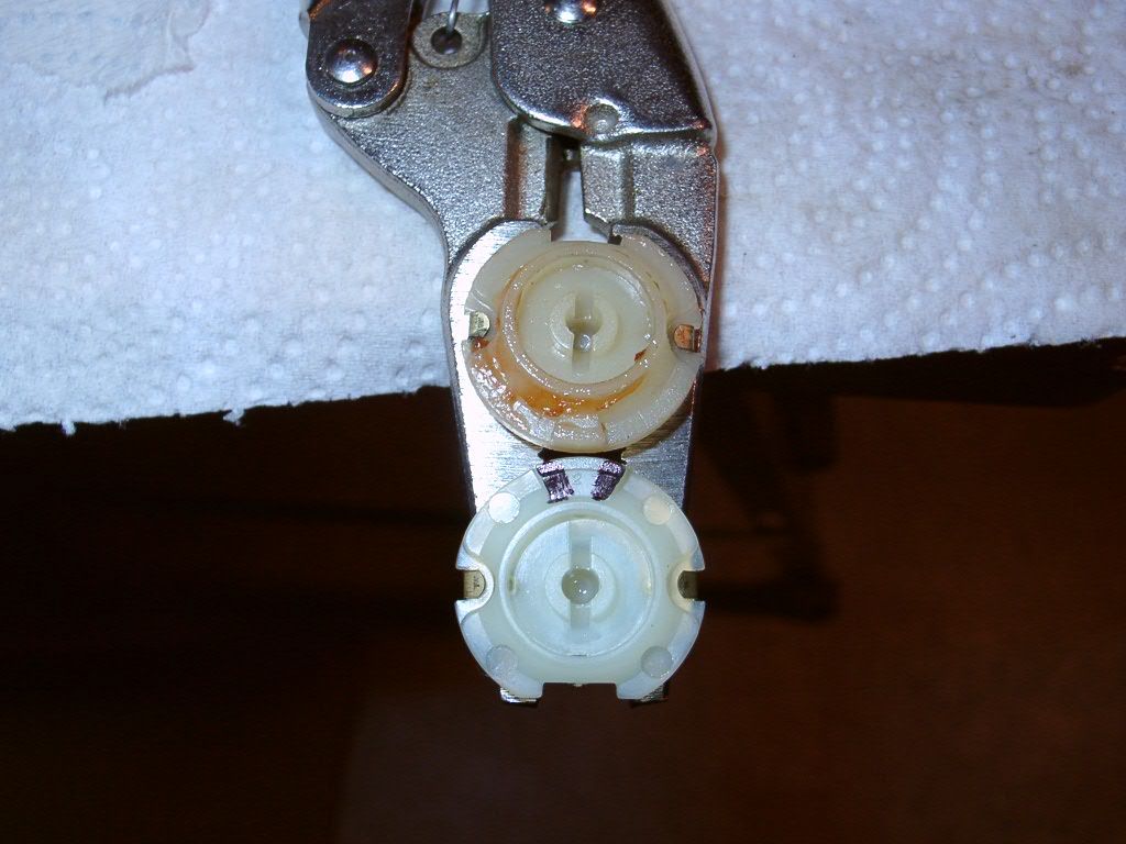
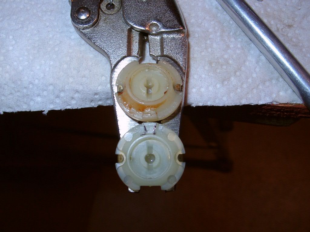
I used an x-acto to carve away the nylon limit stop at the spot highlighted by a black sharpie. This was not hard to do.
After that I put the Atari shaft into the original potentiometer housing and closed it all up. Here is a photo showing the Atari shaft in the controller (the bushing is in backwards here, by the way, but that will be fixed later):
Things seemed smooth enough with the potentiometer check, and the ohm meter confirmed it was working, So I soldered the PCB back onto the wires and proceeded with the power on tests.
Went to hit the switch and it immediately flashed with a loud pop and smoke was released. Then nothing. Dang.
Unplugged it and started the troubleshooting. First I notice that the rectifier is now showing a short between its input terminals. The DIAC and TRIAC are also showing a short from inputs to outputs. What the devil happened????
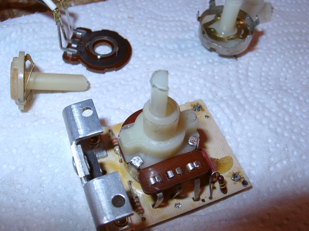
Well I took the potentiometer apart again and found this:
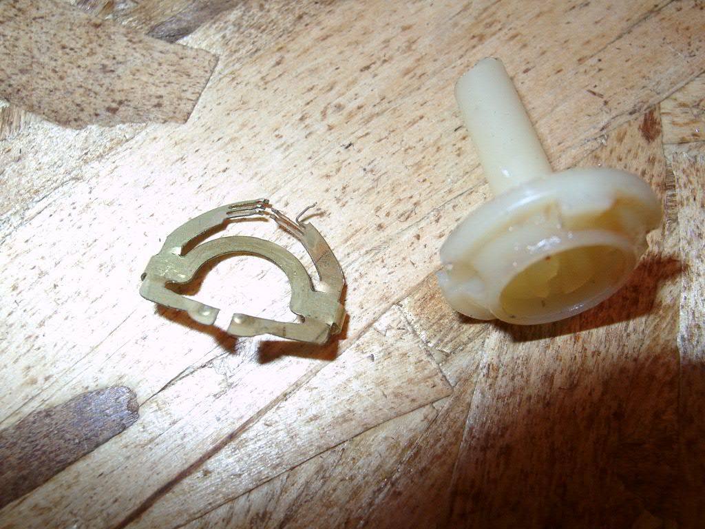
I must have bent the very delicate brush wire upon installation of the Atari shaft. I didn't notice this happening. The bent brush wire then contacted the potentiometer housing. If you've been following along with my posts on this subject, then you should remember that the potentiometer housing is used to bridge the hot input over to the TRIAC. So the full AC line voltage was applied to the DIAC/TRIAC control input pin. The sudden pulse was strong enough to cause the rectifier to also fail.
Now I have the same situation as tdubnik had that started this thread
The bottom of my PCB had vaporized part of the output trace from the TRIAC over to the inductor. That small/thinner portion of the trace conductor must have been designed as a fuse of sorts. If you go back to dusty's photos you can see the thinned down portion of the trace connected to the TRIAC output pin. I didn't have that trace anymore on my damaged board.
This is why I've been away from the topic for the last two weeks. At least I know what to do to fix this thing.
First, I took the good undamaged brush from the original potentiometer shaft and swapped it with the bent Atari brush that shorted to the housing. Then I carefully put the potentiometer back together and made sure it didn't bend a second time. I also checked for shorts to the housing this time around, which is something I should have done the first time knowing that the housing was hot by design.
Second, I ordered a new DIAC, TRIAC and went to my local Radio Shack (which didn't get closed) and picked up a new rectifier module. While I was out shopping I had the additional idea to add a fuse to this circuit. Unfortunately, the only fuse holder that would fit was an automotive style. But I think I can get a regular fuse to fit the automotive fuse holder.
Here is the rectifier and fuse holder I purchased:
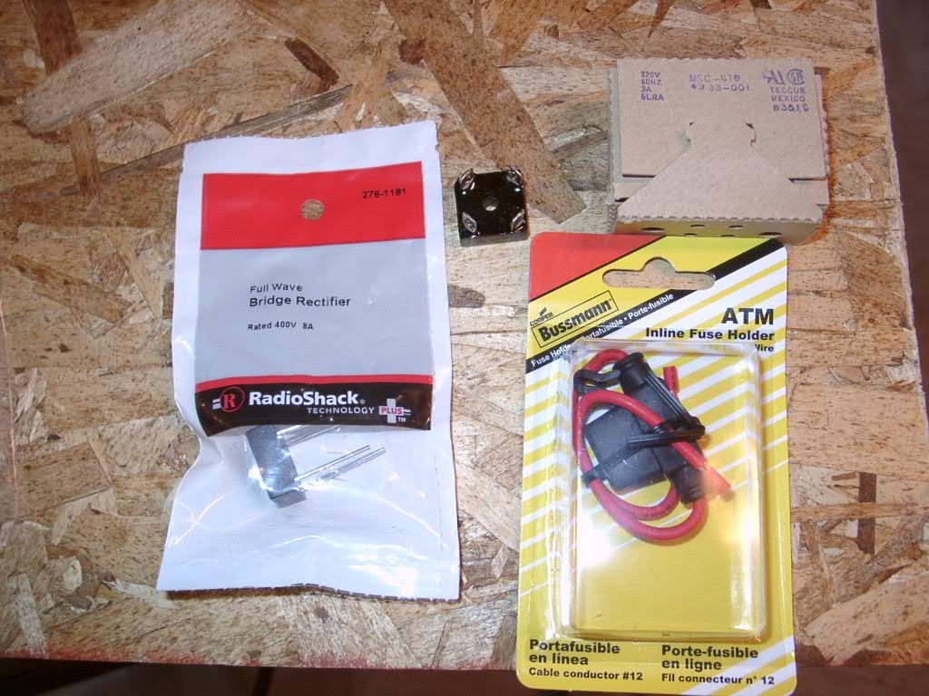
The rectifier is the same exact size as the original, but it has different leads. I trimmed down the leads and soldered the wires to it. The fuse holder was put in place of the white/black stripe wire that connected the control board with the rectifier. Here is a shot of the fuse holder in the controller box:
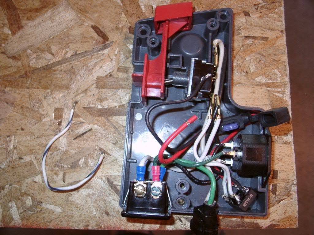
The red wire is the new fuse holder connection that replaced the white/black original wire. Yes, there is an automotive fuse in the fuse holder, but I replaced that with a standard 3 Amp 250V AC fuse in the next photo.
Once the DIAC and TRIAC showed up in a second parts order, I repaired the control board. To repair the vaporized trace, I used one of the cut leads from the rectifier module. That was just the right size to solder onto the bottom of the PCB to make a new connection for the TRIAC output.
Here is a photo of where things stand now:

The NTE DIAC is the same as a DB3 DIAC that are sold for cheap on ebay. I tested these and they had breakover voltage of 32 Volts. That's a bit lower than I originally measured before I blew up my board, but its within the tolerances for these parts (32 +/- 4V).
The proper fuse was used by soldering the leads from an automotive fuse to the glass AC fuse. Its a tight fit, but the rubber cover does close over the assembly. I may try a different way of mounting the fuse as I found soldering the blades to the fuse contacts with the correct alignment to be a bother.
Everything is working again after this ordeal. I'm now going to make some measurements of my DC feed motor speeds and compare that with the published feed rates that the planer is supposed to have. Its my understanding that there are two different feed ranges between different models of the planer.
I have the stand to mount the planer by itself with the 17 amp cutter head motor and the different pulley size upgrade. Now I'm wondering what speeds/feeds I should have given my setup. Figuring out that part is next task.
Sorry for the long post. Hope its helpful for other planer owners in the future.
The NOS potentiometer I ordered showed up and I immediately realized it wouldn't work. The shaft is too short. It was the right style of potentiometer, but the shaft was so short it was hardly any longer than the broken original shaft. So I went back to square one.
It finally dawned on me that the Atari 2600 console from the late 70s/early 80s had paddle controllers with similar potentiometers. Lucky me, I had collected a bunch of these from a garage sale last year which I fixed up and gave out as Christmas gifts to the older generation in my family. Among my big box of Atari parts were non-functional paddle controllers, perfect for parts pirating.
Here is a photo of the Atari paddle controller shaft next to the NOS potentiometer I purchased and also next to the broken original:
The Atari paddle potentiometer shaft isn't an exact replacement, but its close enough. The one thing I changed/modified is to cut away the limit stop to match the original speed controller adjustment range. The next two photos shows the limit stop differences between the Atari shaft with the original (note: the vice grips are NOT marring the shafts, just holding them so I can take the picture):
I used an x-acto to carve away the nylon limit stop at the spot highlighted by a black sharpie. This was not hard to do.
After that I put the Atari shaft into the original potentiometer housing and closed it all up. Here is a photo showing the Atari shaft in the controller (the bushing is in backwards here, by the way, but that will be fixed later):
Things seemed smooth enough with the potentiometer check, and the ohm meter confirmed it was working, So I soldered the PCB back onto the wires and proceeded with the power on tests.
Went to hit the switch and it immediately flashed with a loud pop and smoke was released. Then nothing. Dang.
Unplugged it and started the troubleshooting. First I notice that the rectifier is now showing a short between its input terminals. The DIAC and TRIAC are also showing a short from inputs to outputs. What the devil happened????
Well I took the potentiometer apart again and found this:
I must have bent the very delicate brush wire upon installation of the Atari shaft. I didn't notice this happening. The bent brush wire then contacted the potentiometer housing. If you've been following along with my posts on this subject, then you should remember that the potentiometer housing is used to bridge the hot input over to the TRIAC. So the full AC line voltage was applied to the DIAC/TRIAC control input pin. The sudden pulse was strong enough to cause the rectifier to also fail.
Now I have the same situation as tdubnik had that started this thread
The bottom of my PCB had vaporized part of the output trace from the TRIAC over to the inductor. That small/thinner portion of the trace conductor must have been designed as a fuse of sorts. If you go back to dusty's photos you can see the thinned down portion of the trace connected to the TRIAC output pin. I didn't have that trace anymore on my damaged board.
This is why I've been away from the topic for the last two weeks. At least I know what to do to fix this thing.
First, I took the good undamaged brush from the original potentiometer shaft and swapped it with the bent Atari brush that shorted to the housing. Then I carefully put the potentiometer back together and made sure it didn't bend a second time. I also checked for shorts to the housing this time around, which is something I should have done the first time knowing that the housing was hot by design.
Second, I ordered a new DIAC, TRIAC and went to my local Radio Shack (which didn't get closed) and picked up a new rectifier module. While I was out shopping I had the additional idea to add a fuse to this circuit. Unfortunately, the only fuse holder that would fit was an automotive style. But I think I can get a regular fuse to fit the automotive fuse holder.
Here is the rectifier and fuse holder I purchased:
The rectifier is the same exact size as the original, but it has different leads. I trimmed down the leads and soldered the wires to it. The fuse holder was put in place of the white/black stripe wire that connected the control board with the rectifier. Here is a shot of the fuse holder in the controller box:
The red wire is the new fuse holder connection that replaced the white/black original wire. Yes, there is an automotive fuse in the fuse holder, but I replaced that with a standard 3 Amp 250V AC fuse in the next photo.
Once the DIAC and TRIAC showed up in a second parts order, I repaired the control board. To repair the vaporized trace, I used one of the cut leads from the rectifier module. That was just the right size to solder onto the bottom of the PCB to make a new connection for the TRIAC output.
Here is a photo of where things stand now:
The NTE DIAC is the same as a DB3 DIAC that are sold for cheap on ebay. I tested these and they had breakover voltage of 32 Volts. That's a bit lower than I originally measured before I blew up my board, but its within the tolerances for these parts (32 +/- 4V).
The proper fuse was used by soldering the leads from an automotive fuse to the glass AC fuse. Its a tight fit, but the rubber cover does close over the assembly. I may try a different way of mounting the fuse as I found soldering the blades to the fuse contacts with the correct alignment to be a bother.
Everything is working again after this ordeal. I'm now going to make some measurements of my DC feed motor speeds and compare that with the published feed rates that the planer is supposed to have. Its my understanding that there are two different feed ranges between different models of the planer.
I have the stand to mount the planer by itself with the 17 amp cutter head motor and the different pulley size upgrade. Now I'm wondering what speeds/feeds I should have given my setup. Figuring out that part is next task.
Sorry for the long post. Hope its helpful for other planer owners in the future.