mickyd wrote:Well, the restoration journey has officially begun. I've spent a couple hours...........
The last area that I am having problems with is the motor. I am trying to take it apart to inspect the bearings. I was able to get the front cover off to inspect the front bearing but I can't get the back cover off to check the rear bearing. I think that the rear bearing may be frozen into the back cover and that's the reason I can't get the cover off. I have a post up on the ER10 users site but haven't gotten a response since I posted at 2:PM:( .
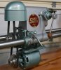
Tonight was motor night. I was able to get the back cover off using a nylon mallet and hitting the motor shaft a few times. That popped the back cover open. As soon as it opened up, I could see why she was turning a bit tight. . [ATTACH]4844[/ATTACH] . [ATTACH]4845[/ATTACH] . The entire back cover is rust. The OD of the bearing is frozen solid in the mating hole.
I think the only way I am going to get the bearing unstuck is a penetrating oil soak??? I ordered a spray can of “Kroil” today so it should be in early next week. Until then, the motor project is on hold.
I still don’t even know if the motor is any good so before I put any money into it, I still need to bench test it. I’m not sure how much of jpg’s procedure1or procedure2applies now that the motor is out so if I could get an update on that, I’d appreciate it.
Yikes! That is some major rust.. I guess you can tell where it spent a long time sitting! After you get the exterior case disassembled it might be time for another round of electrolysis (sans any electronic parts obviously)
Rick
S/W of Los Angeles, CA
1983 Mark V model 510 (SN#140061)
The only thing that affects procedure 1 & 2 is the presence of rust. I do noit think rust is a good insulator. Do a continuity check of the windings after disconnecting the other electrical parts. The readings should be in the very low((< 10 & < 1 ohm) range, and high(near infinity) from windings to frame. I am assumikng there are three wires connected to the windings. Pay attention to which wire goes where and make sure you can identify them later since colors are NOT obvious. Mark them now somehow so as to be able to reconnect them correctly later. Clean as much of the contamination from all other parts as you can.
╔═══╗
╟JPG ╢
╚═══╝
Goldie(Bought New SN 377425)/4" jointer/6" beltsander/12" planer/stripsander/bandsaw/powerstation /Scroll saw/Jig saw /Craftsman 10" ras/Craftsman 6" thicknessplaner/ Dayton10"tablesaw(restoredfromneighborstrashpile)/ Mark VII restoration in 'progress'/ 10E[/size](SN E3779) restoration in progress, a 510 on the back burner and a growing pile of items to be eventually returned to useful life. - aka Red Grange
JPG40504 wrote:The only thing that affects procedure 1 & 2 is the presence of rust. I do noit think rust is a good insulator. Do a continuity check of the windings after disconnecting the other electrical parts. The readings should be in the very low((< 10 & < 1 ohm) range, and high(near infinity) from windings to frame. I am assumikng there are three wires connected to the windings. Pay attention to which wire goes where and make sure you can identify them later since colors are NOT obvious. Mark them now somehow so as to be able to reconnect them correctly later. Clean as much of the contamination from all other parts as you can.
You mention doing the continuity test AFTER disconnecting the other electric parts. This means unsoldering the 1 winding and 1 capacitor wire that connect to the plate, correct? By "plate", I mean the one that the white/black switch wires and white/black winding wires are fastened to with nuts.
You were assuming that there were 3 wires coming off the winding. I don't have the motor with me but in the last photo in my last post above, I see 4. There is a black and white pair that connect to the same posts as the white and black switch wires, 1 black that goes to the capacitor, and 1 black that is soldered to the plate.
Your cautionary note re marking goes without mention.
mickyd wrote:You mention doing the continuity test AFTER disconnecting the other electric parts. This means unsoldering the 1 winding and 1 capacitor wire that connect to the plate, correct? By "plate", I mean the one that the white/black switch wires and white/black winding wires are fastened to with nuts.
You were assuming that there were 3 wires coming off the winding. I don't have the motor with me but in the last photo in my last post above, I see 4. There is a black and white pair that connect to the same posts as the white and black switch wires, 1 black that goes to the capacitor, and 1 black that is soldered to the plate.
Your cautionary note re marking goes without mention.
OK so there are 4 wires. The 'plate' is I believe also part of a centrifugal switch.
Modify the 'continuity' checks to determine if there are two windings(two wires each). Check to frame still applies. there should be some type of flyweight mechanism actuating the 'centrifugal switch'. You need to 'flush' out all the rust to see what is really there!
╔═══╗
╟JPG ╢
╚═══╝
Goldie(Bought New SN 377425)/4" jointer/6" beltsander/12" planer/stripsander/bandsaw/powerstation /Scroll saw/Jig saw /Craftsman 10" ras/Craftsman 6" thicknessplaner/ Dayton10"tablesaw(restoredfromneighborstrashpile)/ Mark VII restoration in 'progress'/ 10E[/size](SN E3779) restoration in progress, a 510 on the back burner and a growing pile of items to be eventually returned to useful life. - aka Red Grange
JPG40504 wrote:OK so there are 4 wires. The 'plate' is I believe also part of a centrifugal switch.
Modify the 'continuity' checks to determine if there are two windings(two wires each). Check to frame still applies. there should be some type of flyweight mechanism actuating the 'centrifugal switch'. You need to 'flush' out all the rust to see what is really there!
Should I unsolder wires connected to the "plate" and the one soldered to the back of the capacitor prior to test?
mickyd wrote:
I've decided that I am going to attempt to recreate a logoplate using a chemical etch process similar to the way a printed circuit board is made. The original.......
I am still going to try to paint the existing faded logoplate..........
One of this weekends project will be my first attempt to reproduce the ER10's logo nameplate. I have all the materials I need to try out the chemical etch process.
1 Qt. bottle of ferric chloride - to etch away the metal sheet stock, $10.00
Master artwork of the logo design - provided by our own tom_k/mo. Thanks Tom!!
20 sheet pack of Press-n-Peel Blue (transfer film that you laser copy a reverse image of the artwork onto) - $40 with shipping. I plan to ebay the leftover sheets and have the proceeds cover the entire cost of the project!:D )
So with this material, a clothes iron or laminator, and a plastic container to the solution, hopefully I'll be able to duplicate the nameplate, raised letters and all.