How would you do this?

This is a forum for intermediate to advanced woodworkers. Show off your projects or share your ideas.

Moderators: HopefulSSer, admin

User avatar
reible
Platinum Member
Posts: 11283
Joined: Thu Jul 20, 2006 12:08 pm
Location: Aurora, IL

Post by reible »

curiousgeorge wrote:Hi Chuck,
Thanks for the atta boy. The belt drive works great. The kit comes with balanced pulleys and with the link belt there is no vibration at all. To adjust the belt tension simply raise or lower the saw table. Like I said earlier, I am going to remove some links from the belt so the table can be lowered to a more workable height.
I am working on a way to hook it up direct with the SPT coupler. The problem is the drum shaft is 1/2".
It may have gotten lost in the transition but the 1/2" shaft size is the same size as is on the jig/scroll saw so a coupler to this shouldn't be a big deal.

Ed
{Knight of the Shopsmith} [Hero's don't wear capes, they wear dog tags]
User avatar
curiousgeorge
Platinum Member
Posts: 880
Joined: Tue Feb 27, 2007 1:00 am
Location: Fort Worth, Texas

Post by curiousgeorge »

reible wrote:It may have gotten lost in the transition but the 1/2" shaft size is the same size as is on the jig/scroll saw so a coupler to this shouldn't be a big deal.

Ed
Ed, I have the coupling kit (555124), but it is for 5/8". I tried to find a coupler for the scroll saw but no joy in mudville. Do you happen to know the P/N for this item?
George
Ft. Worth, TX.
Go TCU Froggies
User avatar
reible
Platinum Member
Posts: 11283
Joined: Thu Jul 20, 2006 12:08 pm
Location: Aurora, IL

Post by reible »

Hi the part I have takes you to another part...
The following is an alternate for the item you searched for
5035769 Accessory Drive Hub


I have no idea if this is the right part but a quick call to shopsmith should clear this up.

Ed
{Knight of the Shopsmith} [Hero's don't wear capes, they wear dog tags]
User avatar
curiousgeorge
Platinum Member
Posts: 880
Joined: Tue Feb 27, 2007 1:00 am
Location: Fort Worth, Texas

Post by curiousgeorge »

reible wrote:Hi the part I have takes you to another part...
The following is an alternate for the item you searched for
5035769 Accessory Drive Hub


I have no idea if this is the right part but a quick call to shopsmith should clear this up.

Ed
Ed,
Thank you, but the 5035769 Accessory Drive Hub is part of the 555124 Power Coupling Kit (http://www.shopsmith.com/ownersite/cata ... oupler.htm) that I already have and only fits a 5/8 shaft. I will just have to call and find out if such an animal exists.
George
Ft. Worth, TX.
Go TCU Froggies
User avatar
reible
Platinum Member
Posts: 11283
Joined: Thu Jul 20, 2006 12:08 pm
Location: Aurora, IL

Post by reible »

{Knight of the Shopsmith} [Hero's don't wear capes, they wear dog tags]
regnar
Gold Member
Posts: 85
Joined: Wed Sep 10, 2008 7:08 pm
Location: Tarpon Springs, FL

Post by regnar »

IF SS doesnt make a coupling that you need you could always go your own route. Im pretty sure these links will help you out. Whats nice about the love-joys is that you would still be able to slide the head out of the way to disconnect. The spider is made out of poly so there is not sharp jolts going though the system.

http://www.use-enco.com/CGI/INPDFF?PMPA ... M=990-4047
"Sua Sponte"
User avatar
allsas
Gold Member
Posts: 157
Joined: Fri Mar 30, 2007 11:48 pm
Location: Kent, WA 98030-8732

V Drum Sander Design ?Collaboration?

Post by allsas »

1. The suggestion for making the table from four parts seems to be a GOOD suggestion. Two middle end pieces with double bevels.

2. WIDER - LONGER single thickness table, to protect the head stock and a wider table to guide the stock.

3. Rails under table to stiffen the single thickness table top. Rails should fit close to the supporting case to aid in aligning the table and throttling the dust collection air flow.

4. Shopsmith direct drive of the sanding cylinder between Headstock and Lathe Tailstock. Pillow blocks / pulley option for a standalone version with an external electrical motor. (Same design, add cleats for pillow blocks).

5. Removable top, no piano hinge. Remove it or drop it in place and hold w/ latches or rare earth magnets on at least 4 leveling bolts into the support case.

6. Add the dust rails to the top not the case. Strengthen the top, with the rails, outside the case and dust rails inside the case.

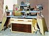
7. Four step setup on SS: 1.....Put case on Way Tubes. 2: Put Sanding Cylinder between Headstock and lathe tail stock. 3. Put top on, over headstock, over sanding cylinder, over tail stock. 4. Tighten case on Way Tubes and hook up input side of leaf blower fot dust extraction.

Look Ma, no outside electrical motor, no pulleys, no link belt. and if you have SHOP SPACE, convert it to standalone. Caution: I think I saw a groove cut into the underside of the top for the belt/pulley on the 2 " SANDING CYLINDER.


Answers to Post #41: >>>
pkni wrote:My top is 3/4 MDF laminated on both sides with 1/8" PVC (i >>>think) coating on one side. The stuff used for cabinet backs in some >>>places.

GOOD Choice

>>>RE your top design: Why not simply use a piano hinge on one side? Or, as >>>someone suggested, use rare earth magnets and shim with metal shims.


>>>A two piece top will be a bear to get aligned with the drum, I would think.
Excellent suggestion: Could use Hanger bolts into case edge and Burrs on upper portion of the hanger bolts to provide about 1/2 inch of static adjustability and dynamic adjustability from the length of hanger bolt lengths ( 1 1/2 " to 3"). Slot in top could be aligned once, leveled occasionally. Top aligns on drop in and latch down if magnetic hold is insufficient. The videos don't show a hinged top getting in the way and a lot of the sandpaper changes occur without tipping the top up. A removable top is suggested to decrease the weight of the components and increase accessibility.

The 1/2 " of static adjustability could be increased by relocating the hanger bolts to the dust rails or the external stability rails where the guide holes for the hanger bolt tops aren't limited to the 3/4 in thickness of the top.

The way tubes and ?1 3/4" ? diameter semicircles in the "end" panels would orient the case consistently and oncenter if the case end panels are cut accurately and held in place by tightening a case hold down (1 x 2 ) under the Way Tubes.


****** I am very interested in experiences building the sanding cylinders ( cylinder material, velcro, and the behavior of the sanding dust. ***** The $258 that PKNI spent to get to a working sander should encourage everyone to build their version of a V drum sander!
MK V 520; MK V 510 w/PP DIY Upgrade; MK 5 500; Jointer; Bandsaw; Sliding Table; Conical Sanding Disk; Sharpening Guide, Lathe Duplicator, Jigsaw, Scrollsaw, Beltsander, Ring Master, Biscuit Joiner.
User avatar
JPG
Platinum Member
Posts: 34642
Joined: Wed Dec 10, 2008 7:42 pm
Location: Lexington, Ky (TAMECAT territory)

503572 = scroll saw hub

Post by JPG »

If the scroll saw is indeed 1/2", this hub will work with SPT coupler. The pn is for the scroll saw.:)
╔═══╗
╟JPG ╢
╚═══╝

Goldie(Bought New SN 377425)/4" jointer/6" beltsander/12" planer/stripsander/bandsaw/powerstation /Scroll saw/Jig saw /Craftsman 10" ras/Craftsman 6" thicknessplaner/ Dayton10"tablesaw(restoredfromneighborstrashpile)/ Mark VII restoration in 'progress'/ 10
E[/size](SN E3779) restoration in progress, a 510 on the back burner and a growing pile of items to be eventually returned to useful life. - aka Red Grange
Gene Howe
Platinum Member
Posts: 3219
Joined: Wed Jul 26, 2006 7:52 pm
Location: Snowflake, AZ

Post by Gene Howe »

I just finished mine from Stock Room and I used a 45deg beveling bit in my router to bevel the underside. If I were doing it again though, I'd make the slot about 2 1/4 wide.

Somewhere on the net, I saw this sander hooked to a SS. It sat on the left table ext. and was driven with the link belt by the accessory shaft. It looked like the motor pulley provided in the kit was used on the accy. shaft.

I really like mine. For a little less than 1/2 of what Sand Flee wants for theirs, I think it was a good deal. All told, I've got $258.00 in mine.
Gene

'The true soldier fights not because he hates what is in front of him, but because he loves what is behind him.' G. K. Chesterton
Ron309753
Gold Member
Posts: 355
Joined: Tue Jul 01, 2008 10:25 pm
Location: Marengo, OH

Post by Ron309753 »

I have been thinking about making a “drum sander in a box” for a couple of weeks now and although I don’t anything drawn up or started here is what I was thinking. For the drum I would use 1.5” diameter PVC with hardwood plugs epoxied in the ends. The drum would mount with the spur and live centers. The box would rest on the main saw table. The top of the box would be split down the middle and hinged on both sides to facilitate drum/grit changes. The sanding table height could be adjusted by adjusting the main table height, and the drum speed adjusted with the speed dial.
A couple of my concerns was what material to use for the top to maintain flatness and the weight I would be putting on the main table.
Any thoughts?

Thanks,

Ron
Post Reply