So with all the talk about Model 10 accessories how did I neglect having a section on one of the most popular accessories made for the Model 10E and Model 10ER. Well it is time to change that. Although it has come up in discussions it really hasn’t been covered all that well. Of course, I am referring to the Speed Changer. It was one of the early accessories made available for the Model 10E. I am not sure just when it was introduced but is in one of the very early accessory catalogs having an unknown date. It is in the later May 1949 accessory catalog too.
EDIT: How could I have neglected adding a picture of the Speed Changer to this post originally. My bad :o
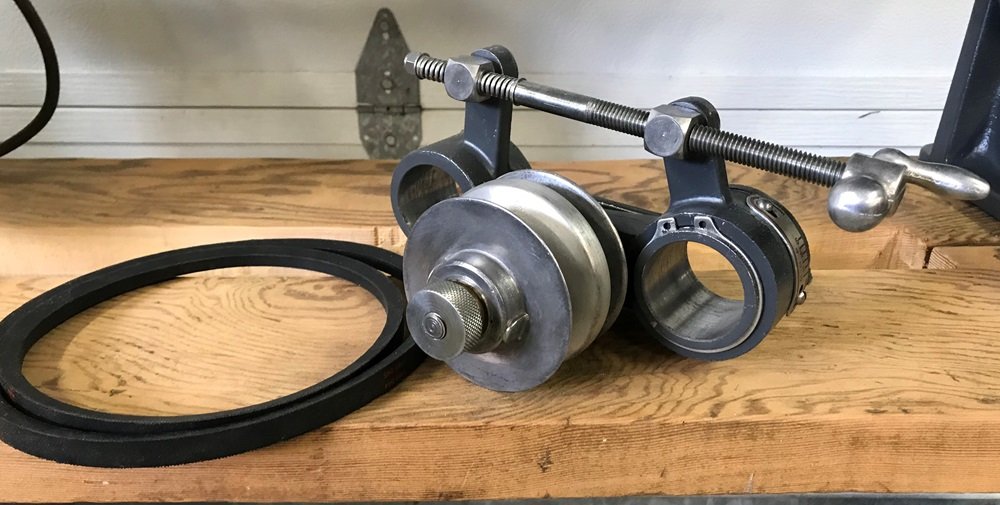
Below is a later Speed Changer. The Crank is mounted away from the Headstock side which keeps the crank from hitting the Headstock Way Tube Lock.
_
.
Just like the Model 10’s it too went through changes during it’s time in production. One of the first was a change to the floating sheave in the pulley. The original ones did not have a sleeve that extended beyond the edge of the floating sheave like later ones had. A noticeable change was to the scale going from 0 to 8 changing to 0 to 5. This change had no effect on the speed range since only 0 to 5 was used on even the early 0 to 8 scale. A very simple change was the way the screw crank assembly came mounted from the factory in later Speed Changers. Moving the crank away from the headstock side of the mounting “ears” also moved the crank away from the headstock’s way tube lock. A simple improvement that can be done on any of the speed changers. Another change was the type of snap ring used to hold the pulley arm on to the main casting. All Speed Changers function the same and the changes didn’t affect that. It still has a range from 425 to 6800 RPM’s when properly adjusted. Below is a PDF of the speed chart and below that is a PDF copy of one of the Manuals for the Speed Changer.
_
Speed Changer Chart.pdf
Variable Speed Changer 01-53 2p plus troubleshooting.pdf
_
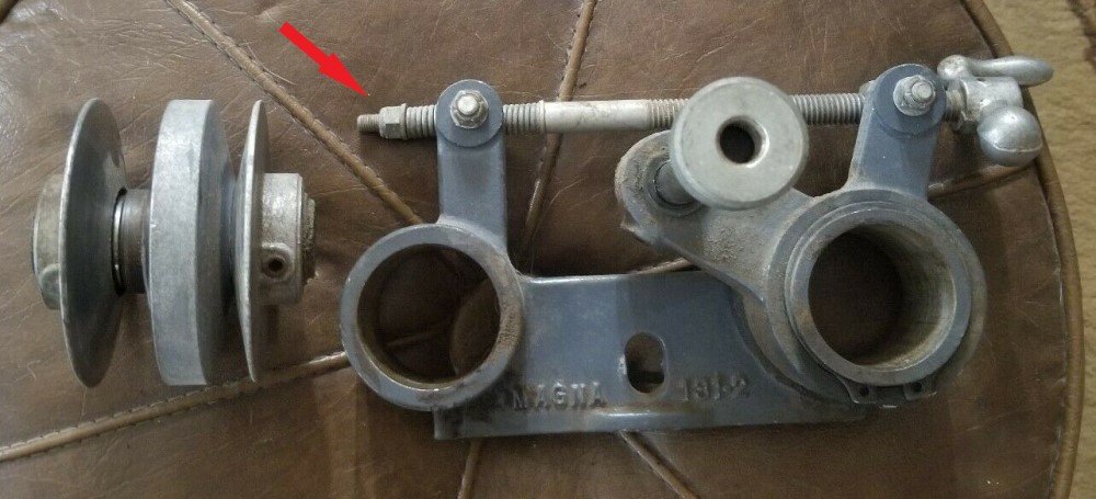
A couple things to know about using the speed changer. Lubrication of the pulley is important both for the oil lite bearings riding on the shaft and the center floating sheave moving back and forth on the sleeve. A good light weight oil will work well. On the end of the crank assembly is a lock nut that holds the springs and end hub in place. Do NOT over tighten the nut, the springs should not be compressed.
EDIT: The arrow in the picture below shows that nut too tight and compressing the springs. This Speed Changer below has the Crank on the Headstock side as they came from the factory early in their production.
_
.
The nut that holds the speed changer to the headstock on the set screw should not be over tightened either. It is only there to keep the speed changer next to the headstock. Moving the headstock with the nut too tight can cause the main casting of the speed changer to break. Although the Manual says setting the Pulley Assembly is a factory job there is no factory to do that adjustment anymore. Remember these were made more than 67 years ago. To be properly set one belt should be low in the pulley but not touch the sleeve and the other belt should be even with the top of the pulley assembly.
Well, I led off with a big build up on this subject but there isn’t all that much I can really tell you about the Speed Changer. Maybe the best part of this entry is having the information in one section. I know from time to time there are some users needing or wanting the manual and/or the speed chart linked above.
The Speed Changer is still one of the most popular accessories made for the Shopsmith Model 10E and 10ER.


