Page 1 of 1
Reassembling a Band Saw (SPTbyJPG)
Posted: Fri Feb 08, 2013 12:10 pm
by JPG
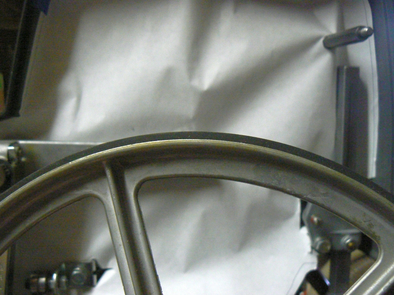
Tore down a recently acquired Band Saw. Added a dust shield(casting is a very efficient dust 'collector/storer'). I did not disassemble the blade guide assemblies, but did clean them up and lube/wax.
I decided to try and eliminate the dust collection 'cubbies' by covering the inside of the casting. I scrounged some butcher paper(from a local butcher shop). I traced the outline of the plastic cover and cut it out a 1/4" outside the line. Not as 'nice' as I had wanted, but the paper is not all in a single flat plane, so 'perfect fit' not attainable nor is 'wrinkle free'. The paper was punctured with an pointed awl to roughly locate the screws etc.
[ATTACH]20183[/ATTACH]
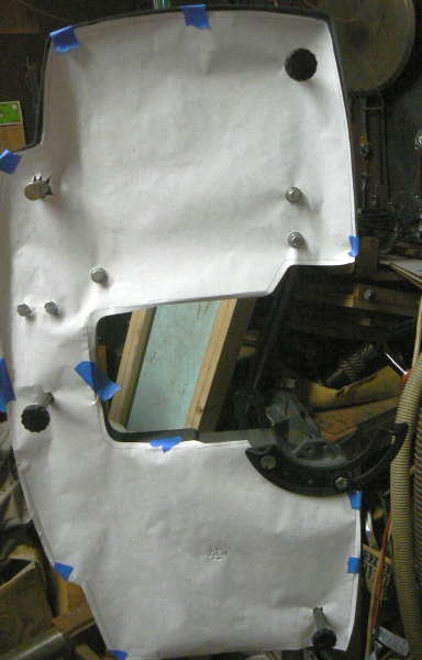
- dust barrier.jpg (206.55 KiB) Viewed 12788 times
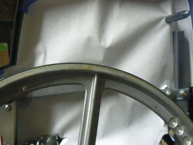
Well if ya should decide to paper yours, I suggest doing the following first(I did not!:o).
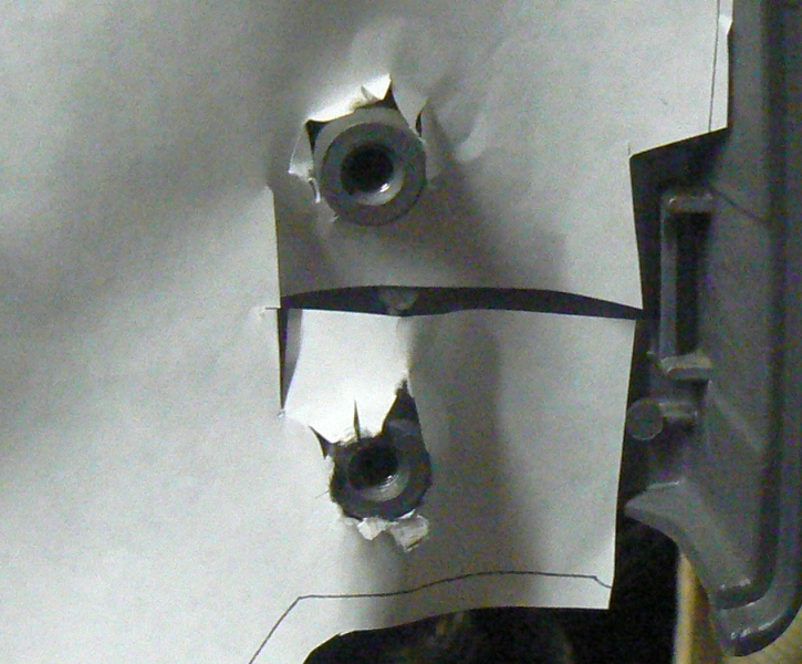
The trunion scale mounting screws use nuts that nest into cavities on the inside of the casting UNDER the trunion. Not a very accessible place for holding nuts. Placing the BS on its casting back eliminates the need to hold them while inserting screws from below. That pointed awl helped get each nut into the cavity.
[ATTACH]20184[/ATTACH]
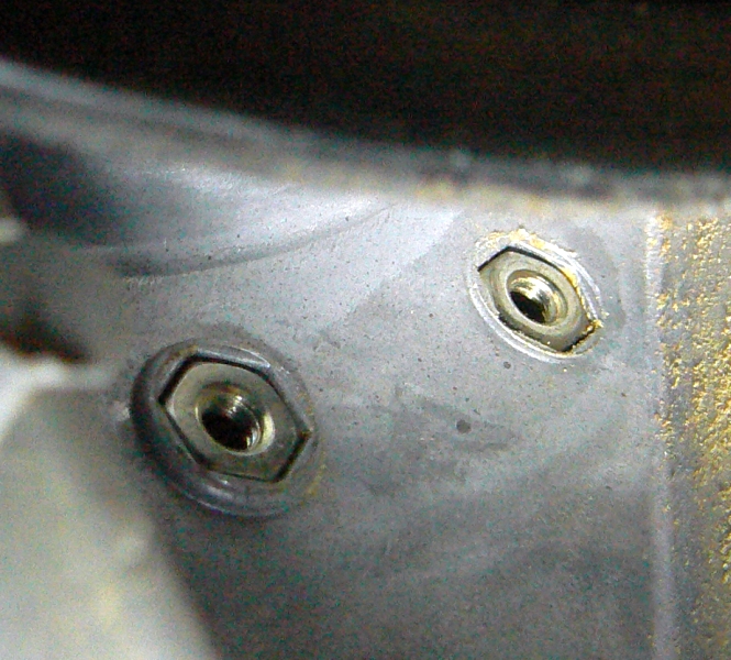
- index nuts.jpg (358.76 KiB) Viewed 12786 times
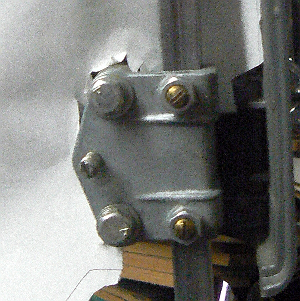
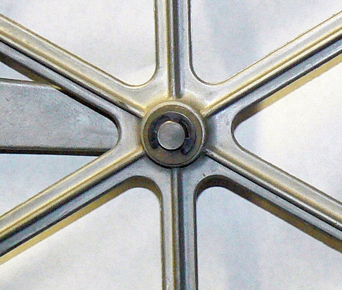
The screws are inserted through a flat washer, through the scale, through the center of the trunion, through the casting and into the nuts. While here notice I replaced the original flat washer that bears against the trunion clamp with a 3/8" fender? washer. It has nearly the same od as the oem washer, but has a much smaller id and centers on the screw whereas the oem washer 'sagged'. I did not show the two washers on the reverse side of the trunion, but they are correctly the same as the oem one.(large id)
[ATTACH]20185[/ATTACH]
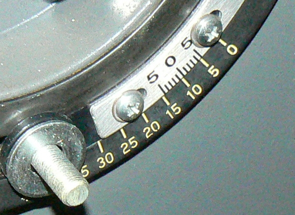
- index plate.jpg (243.98 KiB) Viewed 12791 times
A wave(spring) washer goes on after the washer(I prefer the convex side to face the 'adjuster'. A flat washer goes between the spring washer and the 'adjuster'.
[ATTACH]20186[/ATTACH]
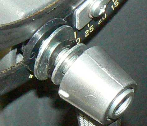
- trunion clamp.jpg (192.24 KiB) Viewed 12793 times
Here is another 'embellishment'. I filled in the truinion scale embossing to make them much more visible to these old eyes.

[ATTACH]20187[/ATTACH]
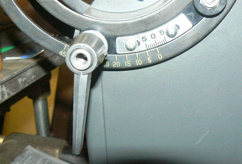
- trunion scale.jpg (376.05 KiB) Viewed 12799 times
Posted: Fri Feb 08, 2013 12:53 pm
by JPG
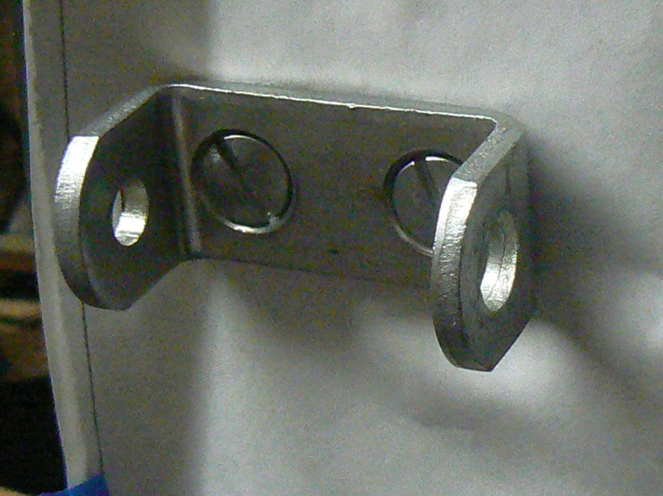
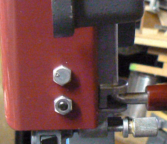
Hokay, back to reassembling! First the tension adjuster bracket. The end with the smaller hole faces the back(left in de pix). Those are large screws with fat slots for a reason, so crank down when tightening. Same goes for the hex standoffs that the cover retaining knobs screw onto. Install them now or whenever.
[ATTACH]20188[/ATTACH]
- tension bracket.jpg (354.48 KiB) Viewed 12785 times
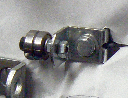
Next I attached the upper guide bearings. They will be adjusted at 'alignment time'. Notice the flat and lock washer
[ATTACH]20189[/ATTACH]
- tracking bearing.jpg (192.44 KiB) Viewed 12786 times
Attach the bar spring to the wheel arm. Snug up only at this time. There is a flat washer under the screw head.
[ATTACH]20190[/ATTACH]
- tension spring.jpg (444.25 KiB) Viewed 12786 times
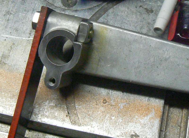
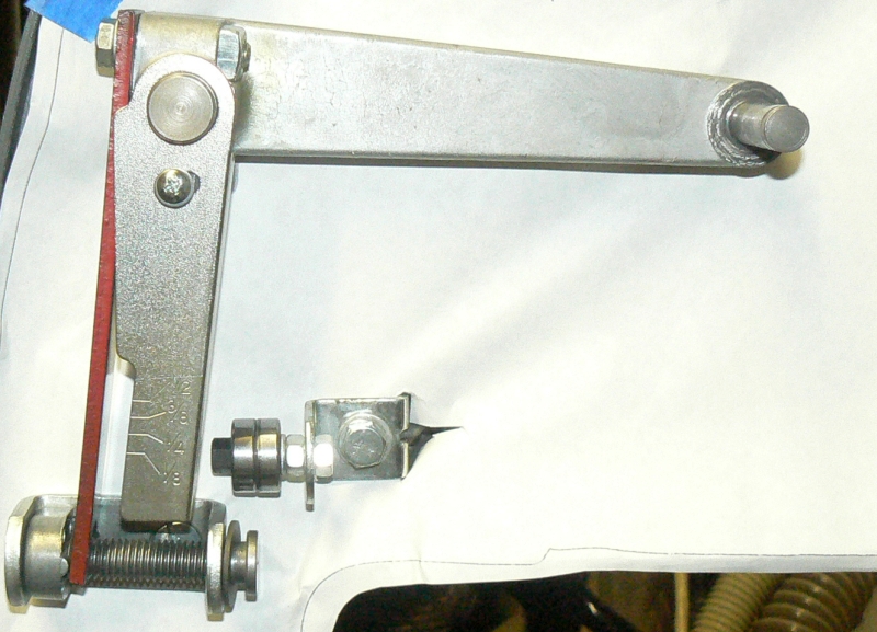
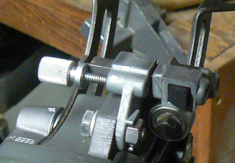
A 'busy' step. Slip the wheel arm onto the pivot shaft. Slip the tension scale on to it next. Secure with screw and flat washer(snug only).
Position the tension adjusting screw
follower just inside the bracket small hole end with the 'nubs' facing towards the spring bar.
Slip the washer over the adjusting screw and insert it into the bracket end with the larger hole. Pass it through the notch in the spring bar. Then thread it into the follower(left hand thread).
[ATTACH]20193[/ATTACH]
- tension scale etc.jpg (350.66 KiB) Viewed 12794 times
Install the retaining clip.
[ATTACH]20194[/ATTACH]
- tension screw clip.jpg (295.44 KiB) Viewed 12779 times
Posted: Fri Feb 08, 2013 1:26 pm
by JPG
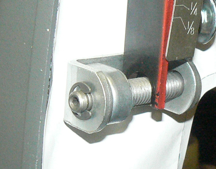
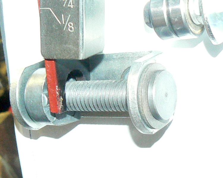
Some adjusting next. Position the spring bar so it is centered about the adjusting screw(so it will not rub), then tighten the spring retaining screw on the wheel arm end(get gorilla like).
Then position the tension scale so that it is positioned to the edge of the spring bar. It should be so at a point near the center and a point near the lower end. Normal torque tightening here.(small screw)
[ATTACH]20195[/ATTACH]
- spring center.jpg (251.69 KiB) Viewed 12779 times
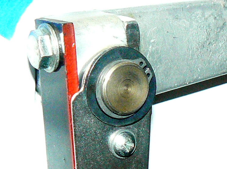
Place the wave(spring) washer on to the pivot shaft(again convex side facing out) and replace retraining ring.
[ATTACH]20196[/ATTACH]
- wheel arm.jpg (306 KiB) Viewed 12777 times
The upper blade guide stuff is attached with two screws, but it also has a bar spring which must seat into the casting near the front.
[ATTACH]20197[/ATTACH]
- upper guide holes.jpg (362.11 KiB) Viewed 12776 times
Make sure the bar spring settles into its nest near the front, and snug up the mounting screws.(flat and lock washers again) The post lock tension can be changed by adjusting the slotted screw(It is helpful if it can be positioned and held there by the lock). Adjusting this beast is to be found elsewhere.(I will point ya to it later)
[ATTACH]20198[/ATTACH]
- upper blade guide.jpg (365.72 KiB) Viewed 12780 times
The lower blade guide assembly mounts with a screw, lock washer and nut. The nut 'slides' in a slot to allow left/right adjustment.(elsewhere again)
[ATTACH]20199[/ATTACH]
- lower blade guide.jpg (361.03 KiB) Viewed 12770 times
Posted: Fri Feb 08, 2013 2:14 pm
by dusty
Worthwhile set of pictures.
Posted: Fri Feb 08, 2013 2:23 pm
by JPG
The lower wheel, shaft and bearing are all one 'part'. It is secured by a notched bracket
similar to the upper bearing guide mounting bracket. A notch fits over a rib in the casting. Screw, lockwasher, bracket. Open ended wrench needed here. Access is a pita.
[ATTACH]20200[/ATTACH]
- lower wheel.jpg (392.46 KiB) Viewed 12764 times
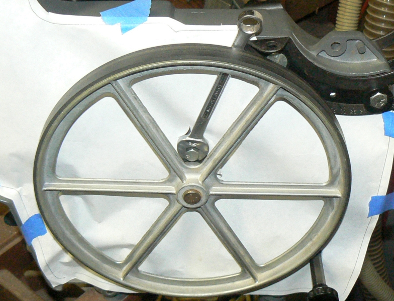
The upper wheel is much easier, but bas ackwards is possible.

[ATTACH]20201[/ATTACH]
- upper wheel front.jpg (392.34 KiB) Viewed 12768 times
The wheel is beveled, so it has an inner side and an outer side. The inner side(mounted towards the casting) is thicker(larger od) than the outer side. The rim is thicker. The tire projection is NOT relevant here!
[ATTACH]20202[/ATTACH]
- upper wheel back.jpg (387.03 KiB) Viewed 12763 times
The upper wheel is retained by a fiber washer and a retaining clip.
[ATTACH]20203[/ATTACH]
- upper wheal.jpg (352.65 KiB) Viewed 12765 times
The blade guard is secured by a screw and a nut
[ATTACH]20204[/ATTACH]
- blade guard.jpg (375.78 KiB) Viewed 12766 times
I will not bore y'all with cover attaching nor mounting the table.
Unless someone asks!;)
Link to adjustment thread to be added here.
https://forum.shopsmith.com/viewtopic.php?t=8542
BTW: The upper blade assembly did NOT have the slop reducing screw. It had very little slop, so I left it like that. Time will tell!
Posted: Fri Feb 08, 2013 2:29 pm
by JPG
dusty wrote:Covering the dust collection points (cubbies) sounds like a great idea - but butcher paper???
If I was going to try this, I think my first thought would have been spray foam. Now I might get a surprise. I've never tried to apply it to a flat surface. My only experience is cracks and crevices around windows, doors, etc.
Butcher paper because: comes in 18" width x ???. It is stiff due to the plastic coating.
I previously used shellacked printer sheets on a planer(Will post when I 'rediscover' the pix:(). The printer paper was large enough for that, but not so the bandsaw.
Adding foam, might deter 'resonance'!:rolleyes:
Re:
Posted: Thu May 11, 2017 12:38 pm
by jjj240
JPG,
As red-lined in my attached figure, SS manual stated to align the red spring with the bracket(?), but you suggested to snug it toward the front, which effectively applying more tension. Is it intentional? or... any other reason?
JPG wrote:Hokay, back to reassembling! First the tension adjuster bracket. The end with the smaller hole faces the back(left in de pix). Those are large screws with fat slots for a reason, so crank down when tightening. Same goes for the hex standoffs that the cover retaining knobs screw onto. Install them now or whenever.
[ATTACH]20188[/ATTACH]
Next I attached the upper guide bearings. They will be adjusted at 'alignment time'. Notice the flat and lock washer
[ATTACH]20189[/ATTACH]
Attach the bar spring to the wheel arm. Snug up only at this time. There is a flat washer under the screw head.
[ATTACH]20190[/ATTACH]
A 'busy' step. Slip the wheel arm onto the pivot shaft. Slip the tension scale on to it next. Secure with screw and flat washer(snug only).
Position the tension adjusting screw follower just inside the bracket small hole end with the 'nubs' facing towards the spring bar.
Slip the washer over the adjusting screw and insert it into the bracket end with the larger hole. Pass it through the notch in the spring bar. Then thread it into the follower(left hand thread).
[ATTACH]20193[/ATTACH]
Install the retaining clip.
[ATTACH]20194[/ATTACH]
Re: Reassembling a Band Saw (SPTbyJPG)
Posted: Thu May 11, 2017 8:41 pm
by JPG
You are getting ahead and misconstruing.
[Attach the bar spring to the wheel arm. Snug up only at this time.]
I was referring to snugging the screw that held the spring 'for now' - it will be tightened in the next post.
The scale will also be adjusted to align with the bar in the next post.
This thread was created when different forum software was used. The pix do not (did not) appear within the text after the current software was adopted. Having all the pix at the end of the post can cause confusion.
I have edited the two posts mentioned and the pix are now in sync with the text. I hope that clears up the confusion. I may edit the other posts in this thread when time permits.
Re: Reassembling a Band Saw (SPTbyJPG)
Posted: Mon May 15, 2017 12:28 am
by jjj240
Somehow, a browser on mobile did not show all the pictures you posted. weird.
Thank you for the clarification.
JPG wrote:You are getting ahead and misconstruing.
[Attach the bar spring to the wheel arm. Snug up only at this time.]
I was referring to snugging the screw that held the spring 'for now' - it will be tightened in the next post.
The scale will also be adjusted to align with the bar in the next post.
This thread was created when different forum software was used. The pix do not (did not) appear within the text after the current software was adopted. Having all the pix at the end of the post can cause confusion.
I have edited the two posts mentioned and the pix are now in sync with the text. I hope that clears up the confusion. I may edit the other posts in this thread when time permits.