I'm a newbie with a used Shopsmith Mark V and I was wondering if someone could explain to me how to mount the accessory table so that it can be adjusted to different heights. At this point the accessory table just bottoms out when I slide into it's base(the left side with the two holes).
I know that the "Accessory Mount Locks" secures the extension table but at this moment I can not figure out how to do it...(I don't know if I am missing a part or if I'm too much of a newb)
I would greatly appreciate any and all help...thanks!
Mark V - How to mount accessory table
Moderator: admin
-
jalisciense
- Bronze Member
- Posts: 6
- Joined: Fri Jan 06, 2012 5:42 pm
You should have what looks like a round handle between those two holes that the accessory table tubes fit in. That is your locking mechanism. As you rotate it, threaded inserts at either end, which are held by guides in the casting, are pushed out against the accessory table's tubes to lock it in place, or they are pulled inward to free the table.jalisciense wrote:I'm a newbie with a used Shopsmith Mark V and I was wondering if someone could explain to me how to mount the accessory table so that it can be adjusted to different heights. At this point the accessory table just bottoms out when I slide into it's base(the left side with the two holes).
I know that the "Accessory Mount Locks" secures the extension table but at this moment I can not figure out how to do it...(I don't know if I am missing a part or if I'm too much of a newb)
I would greatly appreciate any and all help...thanks!
Parts 10, 11, 12 and 21, 22, 23 in this diagram:

Heath
Central Louisiana
-10ER - SN 13927, Born 1949, Acquired October 2008, Restored November, 2008
-10ER - SN 35630, Born 1950, Acquired April 2009, Restored May 2009, A34 Jigsaw
-Mark V - SN 212052, Born 1986, Acquired Sept 2009, Restored March 2010, Bandsaw
-10ER - SN 39722, Born 1950, Acquired March 2011, awaiting restoration
-
JPG

- Platinum Member
- Posts: 35598
- Joined: Wed Dec 10, 2008 7:42 pm
- Location: Lexington, Ky (TAMECAT territory)
The lock consists of three parts. The knurled cylinder, and a square headed screw in each end. One screw is right hand threaded, and the opposite end one is left hand threaded.
If the screws are not adjusted properly(equal projection from the ends), the locks will not be effective.
To adjust, first remove from the end casting. When the screws are 'screwed' close to the ends, the cylinder will slip out with the square heads sliding in a groove in the casting at each end.
Once in hand, rotate the screws until they are all the way into the cylinder(remember one is left handed thread).
After they are both all the way in, back them out about one turn each. This should extend them out enough so the heads will engage both slots in the casting and it can be slid in all the way.
Now the confusing part: Depending upon which way the cylinder was inserted into the slots, rotating the cylinder will either cause the screws to extend further or retract into the cylinder. By rotating in the direction that extends them, the screw heads will pass through holes and into the bore that the table mounting legs are inserted.
Reverse rotation so the screw heads are just out of the bore, and insert the table tubes. Again rotate the cylinder so the screws again extend towards the bore, and they will press against the legs thus holding them in place.
I realize this is a bit lengthy for something so simple, but there are several places to get it wrong! The most important thing is to make sure both screw heads contact the tubes and the cylinder does NOT contact the casting at either end when the tube is locked.
The cylinder etc. can be inserted so pulling up from the outside either tightens of loosens the lock. Reversing the cylinder end for end reverses the action.
╔═══╗
╟JPG ╢
╚═══╝
Goldie(Bought New SN 377425)/4" jointer/6" beltsander/12" planer/stripsander/bandsaw/powerstation /Scroll saw/Jig saw /Craftsman 10" ras/Craftsman 6" thicknessplaner/ Dayton10"tablesaw(restoredfromneighborstrashpile)/ Mark VII restoration in 'progress'/ 10E[/size](SN E3779) restoration in progress, a 510 on the back burner and a growing pile of items to be eventually returned to useful life. - aka Red Grange
-
jalisciense
- Bronze Member
- Posts: 6
- Joined: Fri Jan 06, 2012 5:42 pm

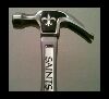
Proverbial
Not everyone can look at those schematics and cipher what they need.
So, here's a pick of the little rascals.
[ATTACH]15824[/ATTACH]
So, here's a pick of the little rascals.
[ATTACH]15824[/ATTACH]
- Attachments
-
- AA Locking Handles.jpg (66.25 KiB) Viewed 1522 times
'55 Greenie #292284 (Mar-55), '89 SS 510 #020989, Mark VII #408551 (sold 10/14/12), SS Band Saw, (SS 500 #36063 (May-79) now gone to son-in-law as of 11-11), Magna bandsaw, Magna jointer 16185 (May-54), Magna belt sander SS28712 (Dec-82), Magna jigsaw SS4397 (Dec-78), SS biscuit joiner, Zyliss (knockoff) vise, 20+ hand planes, 60s Craftsman tablesaw, CarbaTec mini-lathe, and the usual pile of tools. Hermit of the Hills Woodworks, a hillbilly in the foothills of the Ozarks, scraping by.