To start with, let all persons know that I am one of those who redrilled my rear trunnions. I truly believed that doing so made the table easier to align and that its' being smaller than the front trunnion was a manufacturing error.
Despite what Nick has reported, I no longer believe any of that. The Shopsmith designers knew exactly what they were doing.
Keeping in mind that what you are doing when you align the table is moving the table to a position where the miter track(s) are parallel to the blade. The orientation of the blade, with respect to the tubes, is fixed (perpendicular to the tubes.
If you lock the position of any point on the table and rotate the table around that point, there will be a position where the miter slot will be parallel to the blade. Enlarging that hole, in my opinion, complicates the process of finding that position of parallelism and at the same time makes it more difficult to maintain that positionwhen securing the bolts.
Side Comment: Any one of the four trunnion holes could/can be used for this alignment because they are symmetrically located around the blade.
I have used Sketchup to monitor what happens to the various dimensions when the table is repositioned. This exercise was very interesting. I would encourage the Sketchup users to play with this but only if you have some time to lose. I spent a couple hours on it.
Main Table Alignment and Trunnion Bolts
Moderator: admin
-
dusty

- Platinum Member
- Posts: 21530
- Joined: Wed Nov 22, 2006 6:52 am
- Location: Tucson (Wildcat Country), Arizona
Main Table Alignment and Trunnion Bolts
"Making Sawdust Safely"
Dusty
Sent from my Dell XPS using Firefox.
Dusty
Sent from my Dell XPS using Firefox.
-
Ed in Tampa

- Platinum Member
- Posts: 5834
- Joined: Fri Jul 21, 2006 12:45 am
- Location: North Tampa Bay area Florida
I too enlarged the hole on my trunion and I'm now convinced it was a mistake.dusty wrote:To start with, let all persons know that I am one of those who redrilled my rear trunnions. I truly believed that doing so made the table easier to align and that its' being smaller than the front trunnion was a manufacturing error.
Despite what Nick has reported, I no longer believe any of that. The Shopsmith designers knew exactly what they were doing.
Keeping in mind that what you are doing when you align the table is moving the table to a position where the miter track(s) are parallel to the blade. The orientation of the blade, with respect to the tubes, is fixed (perpendicular to the tubes.
If you lock the position of any point on the table and rotate the table around that point, there will be a position where the miter slot will be parallel to the blade. Enlarging that hole, in my opinion, complicates the process of finding that position of parallelism and at the same time makes it more difficult to maintain that positionwhen securing the bolts.
Side Comment: Any one of the four trunnion holes could/can be used for this alignment because they are symmetrically located around the blade.
I have used Sketchup to monitor what happens to the various dimensions when the table is repositioned. This exercise was very interesting. I would encourage the Sketchup users to play with this but only if you have some time to lose. I spent a couple hours on it.
I can't find it but I'm almost totally certain that the original table alignment procedures that I followed when I first got my Shopsmith said to carefully (as in not too much) loosen that specific bolt (rear trunion the left most or the bolt closest to the headstock) and loosen the other three enough to move the table.
I think what enlarging the hole does is allow the user to move the table so that while parallel to the blade the blade is not perfectly centered in the insert slot.
I think if you try to center the blade in the slot with the arbor retracted all the way and carriage pushed against the black ring stop while maintaining parallelism you will find it much harder than before the trunnion bolt hole was drilled out.
Well live and learn as they say.
One thing in my favor is I do have a whole main table, support tube trunion assemble that has not been drilled. I may just swap it with the one I'm using to see what differences it makes.
If I do I will report back.
Ed in Tampa
Stay out of trouble!
Stay out of trouble!
-
JPG

- Platinum Member
- Posts: 35600
- Joined: Wed Dec 10, 2008 7:42 pm
- Location: Lexington, Ky (TAMECAT territory)
If you want to spend more time with sketchup, return the 'left rear' hole to the 'original size' and notice what happens with the other rear hole as the table is 'rotated.
I can understand having one 'tight' hole to pivot on. The other three holes need to be larger to enable said rotation.
Cannot a sleeve be used on the 'pivot' screw to 'tighten' things at that one hole?
I cannot get worked up over centering the blade front to rear in the slot.
I can understand having one 'tight' hole to pivot on. The other three holes need to be larger to enable said rotation.
Cannot a sleeve be used on the 'pivot' screw to 'tighten' things at that one hole?
I cannot get worked up over centering the blade front to rear in the slot.
╔═══╗
╟JPG ╢
╚═══╝
Goldie(Bought New SN 377425)/4" jointer/6" beltsander/12" planer/stripsander/bandsaw/powerstation /Scroll saw/Jig saw /Craftsman 10" ras/Craftsman 6" thicknessplaner/ Dayton10"tablesaw(restoredfromneighborstrashpile)/ Mark VII restoration in 'progress'/ 10E[/size](SN E3779) restoration in progress, a 510 on the back burner and a growing pile of items to be eventually returned to useful life. - aka Red Grange
╟JPG ╢
╚═══╝
Goldie(Bought New SN 377425)/4" jointer/6" beltsander/12" planer/stripsander/bandsaw/powerstation /Scroll saw/Jig saw /Craftsman 10" ras/Craftsman 6" thicknessplaner/ Dayton10"tablesaw(restoredfromneighborstrashpile)/ Mark VII restoration in 'progress'/ 10E[/size](SN E3779) restoration in progress, a 510 on the back burner and a growing pile of items to be eventually returned to useful life. - aka Red Grange

While we each might have our own opinions on the hole size the facts are that shopsmith has been willing to replace this piece as a defective part. If it was done as part of a redesign that has been lost, well who knows? Current parts have the same size holes (unless someone finds out other wise).
Since I was one who had a "problem" part I know that it was much more difficult to align that table. I didn't know why but it did, then came some posts here with others having problems, some of which seemed to be related to the "under sized hole". When I drilled mine out it became much easier to do the alignment.
Remember the requirement is the have the plane of the blade parallel to the miter gauge slots. There is no requirement that the blade be centered in the table. However since the holes verses the bolts will only allow for limited movement tells you that the blade will be close.
Now lets discuss how close. If all parts were made such that all holes and I mean table and trunnion were right on with out any tolerance I guess the design has the blade right in the center. Even this statement would be questionable because we have no idea if that would be to the center of the blade, or right side or left side and that is just the start of those issues. Without access to the shopsmith drawing it would be only guessing.
Now lets talk about some of the things that effect say the holes in the table for a brief moment. Each of the 4 holes could have a tolerance to some location on the table, or they could be referenced to each other then referenced to a point/edge/hole. You can be sure they have some tolerance specified on the shopsmith drawings and they will be referenced to some point, also with a tolerance. In addition to the there maybe tolerances for rotation and how vertical they are. The size of the holes will also appear with a tolerance or an implied one, like wise information for tapping and how deep it is drilled then tapped.
For grins now lets talk about tolerances, the tighter you make them the more difficult getting it is to make parts that meet them. As an example lets imaging two hole that need to be 10" apart on two pieces that fit together. Now say I allow the distance between holes to be off by 1/4" by specifying +/- 1/8". This means the holes could be to far apart by 1/4", 10-1/4" when measured. It also means the second part could be off the other way by 1/4" or 9-3/4" between the holes. Now when I want to put the parts together the holes could be off as much as 1/2". Now if the holes were say drilled with a letter "F" drill and a 1/4" bolt was going to be used to fasten them together at both holes we have two parts that don't fit.
If in the above case we were to make the hole a little larger it would still not likely fit, a slot might work pretty good as we could make the slot long enough so that they would fit. The other option is to change the tolerance between the holes. Let's say we make it .001" or plus or minus .0005". and say we enlarge the hole to 9/32". Now the two parts would always fit but now it will be very difficult for the person making this to keep the holes within this tolerance, most likely not being able to do it all the time. More parts would be rejected and the waste will rise.
So effort has to be put into the design of parts so they can be made without controlling the heck out of them and have the most useable parts when you are done. Of course that is making this over simplified, when you have more then one part the whole process has to be done for assemblies which is most often the case at a factory.
So we can guess all we want but without engineering this we could not be sure what the real situation is. Say the hole is left smaller, some table will then fit well with the situation and alignment is easier, but it also could be that some table will not be able to be aligned at all. This is/was shopsmith call and unless they do the work and proclaim it is better with the small hole who are we to out guess them.
I'm a little picky on this subject because I was on the other side and designed a lot of parts and assemblies and selected parts and used parts depending on other peoples/companies holding tolerances. In the old days this was all hand done and I could not guess the hours I spent doing this sort of work.
One of the other less fun parts of my job was when they would offer incentives to the factory people to find ways of saving money on our products. All they had to do was right down an idea and then we would have to select what to do with the idea. Yes there were some ideas were valid especially when they had to do with assembly or the likes which we could accommodate and do. But then we would get things like putting in a smaller (physical size) resistor and getting rid of the shield cause it wouldn't be so hot anymore???? I remember this one because it was a 90W screw in resistor used to dissipate a contactor with 3600uf 200v cap... If I remember right they were really pushing this so I gave them a 20 watt and said try it yourself. Never heard back from them, I'm guessing the pieces of flying ceramic damped there desire to remove the the guard as well.
So bottom line here is that if you want to go back to a smaller hole you can do so by buying a bushing of the correct size and using that. I forgot the sizes, now 1/2" was 3/8"??? and if necessary or if you desire the bushing could be sized by drilling to some other dimensions.
So now I've had my say I'll climb back in my hole and let you enjoy your thoughts on the subject.
Ed
Since I was one who had a "problem" part I know that it was much more difficult to align that table. I didn't know why but it did, then came some posts here with others having problems, some of which seemed to be related to the "under sized hole". When I drilled mine out it became much easier to do the alignment.
Remember the requirement is the have the plane of the blade parallel to the miter gauge slots. There is no requirement that the blade be centered in the table. However since the holes verses the bolts will only allow for limited movement tells you that the blade will be close.
Now lets discuss how close. If all parts were made such that all holes and I mean table and trunnion were right on with out any tolerance I guess the design has the blade right in the center. Even this statement would be questionable because we have no idea if that would be to the center of the blade, or right side or left side and that is just the start of those issues. Without access to the shopsmith drawing it would be only guessing.
Now lets talk about some of the things that effect say the holes in the table for a brief moment. Each of the 4 holes could have a tolerance to some location on the table, or they could be referenced to each other then referenced to a point/edge/hole. You can be sure they have some tolerance specified on the shopsmith drawings and they will be referenced to some point, also with a tolerance. In addition to the there maybe tolerances for rotation and how vertical they are. The size of the holes will also appear with a tolerance or an implied one, like wise information for tapping and how deep it is drilled then tapped.
For grins now lets talk about tolerances, the tighter you make them the more difficult getting it is to make parts that meet them. As an example lets imaging two hole that need to be 10" apart on two pieces that fit together. Now say I allow the distance between holes to be off by 1/4" by specifying +/- 1/8". This means the holes could be to far apart by 1/4", 10-1/4" when measured. It also means the second part could be off the other way by 1/4" or 9-3/4" between the holes. Now when I want to put the parts together the holes could be off as much as 1/2". Now if the holes were say drilled with a letter "F" drill and a 1/4" bolt was going to be used to fasten them together at both holes we have two parts that don't fit.
If in the above case we were to make the hole a little larger it would still not likely fit, a slot might work pretty good as we could make the slot long enough so that they would fit. The other option is to change the tolerance between the holes. Let's say we make it .001" or plus or minus .0005". and say we enlarge the hole to 9/32". Now the two parts would always fit but now it will be very difficult for the person making this to keep the holes within this tolerance, most likely not being able to do it all the time. More parts would be rejected and the waste will rise.
So effort has to be put into the design of parts so they can be made without controlling the heck out of them and have the most useable parts when you are done. Of course that is making this over simplified, when you have more then one part the whole process has to be done for assemblies which is most often the case at a factory.
So we can guess all we want but without engineering this we could not be sure what the real situation is. Say the hole is left smaller, some table will then fit well with the situation and alignment is easier, but it also could be that some table will not be able to be aligned at all. This is/was shopsmith call and unless they do the work and proclaim it is better with the small hole who are we to out guess them.
I'm a little picky on this subject because I was on the other side and designed a lot of parts and assemblies and selected parts and used parts depending on other peoples/companies holding tolerances. In the old days this was all hand done and I could not guess the hours I spent doing this sort of work.
One of the other less fun parts of my job was when they would offer incentives to the factory people to find ways of saving money on our products. All they had to do was right down an idea and then we would have to select what to do with the idea. Yes there were some ideas were valid especially when they had to do with assembly or the likes which we could accommodate and do. But then we would get things like putting in a smaller (physical size) resistor and getting rid of the shield cause it wouldn't be so hot anymore???? I remember this one because it was a 90W screw in resistor used to dissipate a contactor with 3600uf 200v cap... If I remember right they were really pushing this so I gave them a 20 watt and said try it yourself. Never heard back from them, I'm guessing the pieces of flying ceramic damped there desire to remove the the guard as well.
So bottom line here is that if you want to go back to a smaller hole you can do so by buying a bushing of the correct size and using that. I forgot the sizes, now 1/2" was 3/8"??? and if necessary or if you desire the bushing could be sized by drilling to some other dimensions.
So now I've had my say I'll climb back in my hole and let you enjoy your thoughts on the subject.
Ed
-
JPG
- Platinum Member
- Posts: 35600
- Joined: Wed Dec 10, 2008 7:42 pm
- Location: Lexington, Ky (TAMECAT territory)
Ditto what Ed said!;):)

╔═══╗
╟JPG ╢
╚═══╝
Goldie(Bought New SN 377425)/4" jointer/6" beltsander/12" planer/stripsander/bandsaw/powerstation /Scroll saw/Jig saw /Craftsman 10" ras/Craftsman 6" thicknessplaner/ Dayton10"tablesaw(restoredfromneighborstrashpile)/ Mark VII restoration in 'progress'/ 10E[/size](SN E3779) restoration in progress, a 510 on the back burner and a growing pile of items to be eventually returned to useful life. - aka Red Grange
╟JPG ╢
╚═══╝
Goldie(Bought New SN 377425)/4" jointer/6" beltsander/12" planer/stripsander/bandsaw/powerstation /Scroll saw/Jig saw /Craftsman 10" ras/Craftsman 6" thicknessplaner/ Dayton10"tablesaw(restoredfromneighborstrashpile)/ Mark VII restoration in 'progress'/ 10E[/size](SN E3779) restoration in progress, a 510 on the back burner and a growing pile of items to be eventually returned to useful life. - aka Red Grange
-
Ed in Tampa
- Platinum Member
- Posts: 5834
- Joined: Fri Jul 21, 2006 12:45 am
- Location: North Tampa Bay area Florida
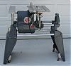
I would like to jump in here now. I have made and machined dozens of metal parts with rotating shafts and bearings. I found with any 4 bolt design, I needed to make one bolt hole a tight fit on the bolt and over size the other 3 holes. I found with 4 oversize holes, the part with the holes will tend to move somewhat over time even with gaskets, sealers and lockwashers. It appeared that the one tight fitting bolt prevented later misalignment but allowed alignment originally. This may not relate to your table alignment problems but I only made 3 of the trunnion bracket holes over size to help me with all the table alignments. This appears to have worked for me.
Bill Mayo bill.mayo@verizon.net
Shopsmith owner since 73. Sell, repair and rebuild Shopsmith, Total Shop & Wood Master headstocks, SPTs, attachments, accessories and parts. US Navy 1955-1975 (FTCS/E-8)
Shopsmith owner since 73. Sell, repair and rebuild Shopsmith, Total Shop & Wood Master headstocks, SPTs, attachments, accessories and parts. US Navy 1955-1975 (FTCS/E-8)
-
Ed in Tampa
- Platinum Member
- Posts: 5834
- Joined: Fri Jul 21, 2006 12:45 am
- Location: North Tampa Bay area Florida
billmayo wrote:I would like to jump in here now. I have made and machined dozens of metal parts with rotating shafts and bearings. I found with any 4 bolt design, I needed to make one bolt hole a tight fit on the bolt and over size the other 3 holes. I found with 4 oversize holes, the part with the holes will tend to move somewhat over time even with gaskets, sealers and lockwashers. It appeared that the one tight fitting bolt prevented later misalignment but allowed alignment originally. This may not relate to your table alignment problems but I only made 3 of the trunnion bracket holes over size to help me with all the table alignments. This appears to have worked for me.
Now that is an interesting observation. And it may explain a few things that I have been experiencing. I wonder if I could insert a bushing in the trunnion hole I enlarged and redrill it to the original size whatever that was?
Hate to lose a spare trunnion because I rushed to do something.
Any thoughts.
Ed in Tampa
Stay out of trouble!
Stay out of trouble!
-
JPG
- Platinum Member
- Posts: 35600
- Joined: Wed Dec 10, 2008 7:42 pm
- Location: Lexington, Ky (TAMECAT territory)
'Somebody' back in post #3 thought so.Ed in Tampa wrote:Now that is an interesting observation. And it may explain a few things that I have been experiencing. I wonder if I could insert a bushing in the trunnion hole I enlarged and redrill it to the original size whatever that was?
Hate to lose a spare trunnion because I rushed to do something.
Any thoughts.
 I believe the screws are 3/8". So 25/64"? I would get a 1/2 x3/8 sleeve. Or were the holes drilled out to 7/16"? If so, drill out to 1/2 and sleeve.
╔═══╗
╟JPG ╢
╚═══╝
Goldie(Bought New SN 377425)/4" jointer/6" beltsander/12" planer/stripsander/bandsaw/powerstation /Scroll saw/Jig saw /Craftsman 10" ras/Craftsman 6" thicknessplaner/ Dayton10"tablesaw(restoredfromneighborstrashpile)/ Mark VII restoration in 'progress'/ 10E[/size](SN E3779) restoration in progress, a 510 on the back burner and a growing pile of items to be eventually returned to useful life. - aka Red Grange
╟JPG ╢
╚═══╝
Goldie(Bought New SN 377425)/4" jointer/6" beltsander/12" planer/stripsander/bandsaw/powerstation /Scroll saw/Jig saw /Craftsman 10" ras/Craftsman 6" thicknessplaner/ Dayton10"tablesaw(restoredfromneighborstrashpile)/ Mark VII restoration in 'progress'/ 10E[/size](SN E3779) restoration in progress, a 510 on the back burner and a growing pile of items to be eventually returned to useful life. - aka Red Grange