Is knot it odd that we can be made to feel guilty about maintenance of our SS? BTW, I, too, use a dehumidifier, and I find that it helps keep the moisture problems which lead to rust and mold completely at bay. I get at least a gallon of water every day, out of my basement, and the humidity level in my house stays around 40% year round. Of course, I live in a very wet Pacific NW, and my outside humidity level is usually much higher then 40%.tdubnik wrote:I bought the Shopsmith with the jointer, bandsaw and belt sander in the late 70s. I added the planer and strip sander a few years later. It has been in my basement for the past 20 years and didn't see much use for a long time. I started some remodeling projects a couple of years ago and started using it more.
I had a leak in my basement a few years ago the the environment was damp for a little while. I had the problem fixed and added a dehumidifier and the environment is good now. I got most everything cleaned up and the tools steel-wooled and waxed but I guess I didn't get around to the drill chuck.
Pro Planer speed control box problem
Moderators: HopefulSSer, admin
-
a1gutterman

- Platinum Member
- Posts: 3653
- Joined: Tue Jan 09, 2007 12:45 am
- Location: "close to" Seattle
Tim
Buying US made products will help keep YOUR job or retirement funds safer.
Buying US made products will help keep YOUR job or retirement funds safer.
-
RobertTaylor

- Platinum Member
- Posts: 560
- Joined: Mon Sep 03, 2007 9:28 am
- Location: North Canton, Ohio
excellent repair. i know hindsight is always 20/20. i probably would have flipped the piece of the box that you cut out over and glued it to the front of the box. or at least the back or flat portion of it. but a great job none the less.
Bob
1954 greenie, 1963 anniversary edition now a mini,
1984 500, 1985 510, 1987 510, pro-planer, bandsaw, dust collector
1954 greenie, 1963 anniversary edition now a mini,
1984 500, 1985 510, 1987 510, pro-planer, bandsaw, dust collector
There always has to be a yang to the yin. - - I have a humidifier in my house. We put a gallon into the air every day. Our indoor humidity stays around 45%. (outdoor relative humidity today was around 8%)a1gutterman wrote:.... I get at least a gallon of water every day, out of my basement, and the humidity level in my house stays around 40% year round. Of course, I live in a very wet Pacific NW, and my outside humidity level is usually much higher then 40%.
Tdubnik - CONGRATULATIONS!! That was the completion of what has been probably the most talked about project in the Forum. You did good to keep your mind wrapped around this and hang on until completion. And a darn fine job too! Here's your ATTA BOY!!!!!
Octogenarian's have an earned right to be a curmudgeon.
Chuck in Lancaster, CA
Chuck in Lancaster, CA
Good to see that you got it all working. This thread should be useful to others who experience problems with the feed motor speed control.tdubnik wrote: In the end the total cost of my rebuild was $2.49 for the rectifier and $4.95 for the dimmer switch. In addition the time spent on this thread and research were the only other things required.
I want to thank everyone who participated in this thread and especially all of the ideas that were contributed. I don't think I would have been successful without your help!!!
It sounds like the Pro Planer is an awesome piece of machinery. I'll save my pennies for one in the future. Glad to be of help.
Happy woodworking!
John Mallick
Dripping Springs, TX
Beginning Woodworker
Passable Barbecue'er
Dripping Springs, TX
Beginning Woodworker
Passable Barbecue'er
WOW!! and THANK YOU ALL!!!!!
That was as fascinating as ANY Agatha Christie novel!!!! The Butler did it, in the library, with a lead pipe! 
Charlie - Danbury Ct.
510, planer, jointer, belt sander and bandsaw.
510, planer, jointer, belt sander and bandsaw.
Thought I would update this post as well as the one on my squealing problem.
Since I have started working on my workbench, I have given my planer heavy use. I ahve been planing 12/4 poplar and 8/4 hard maple with nary a complaint. The planer is working very well and the speed control is working properly. It seems that my fix is robust enough to handle what I have thrown at it to date. Between yesterday and today I have run it for more than 6 hours planing the boards for my workbench top. The maple I have is somewhat figured so I am taking small slow passes. I have planed off roughly 1/2" taking 1/32" bites. I start running the speed at around 7 or 8 and then for the last couple of passes I slow down to 4 to get the best finish possible.
Since I have started working on my workbench, I have given my planer heavy use. I ahve been planing 12/4 poplar and 8/4 hard maple with nary a complaint. The planer is working very well and the speed control is working properly. It seems that my fix is robust enough to handle what I have thrown at it to date. Between yesterday and today I have run it for more than 6 hours planing the boards for my workbench top. The maple I have is somewhat figured so I am taking small slow passes. I have planed off roughly 1/2" taking 1/32" bites. I start running the speed at around 7 or 8 and then for the last couple of passes I slow down to 4 to get the best finish possible.
-
dj1960gold
- Silver Member
- Posts: 17
- Joined: Wed Mar 26, 2014 11:34 pm
- Location: Denver Colorado
Re: Pro Planer speed control box problem
Better late than never 
I read all 106 posts in this thread and didn't see a circuit diagram for the feed motor speed controller. I recently purchased a used 1983 M5990 planer that had its control knob broken off (among other small problems).
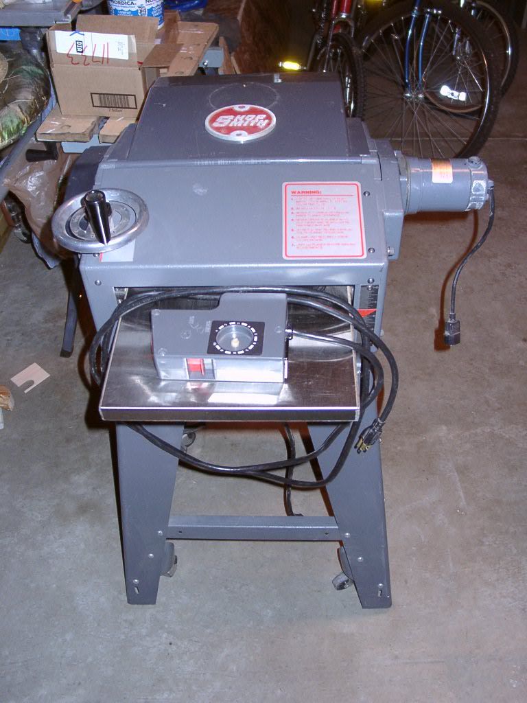
The control box still functions, but its rather difficult to turn the small piece of nylon shaft that still remains on my new tool.
So before taking things apart, check the forum to see what other SS owners have done. And sure enough the control box is a topic of discussion here
I have the other style of DC motor speed controller, same as dusty posted here on page 8 of this thread. Here is a photo of the start of the breakdown process of my box:
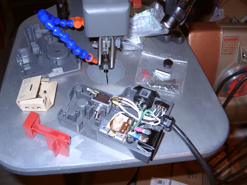
This speed controller has a few more small parts than tdubnik's fried controller. What's the difference? I think the answer is that I have the original Mark V regular planer on an upgraded power stand, and tdubnik has an actual Pro Planer. There is a small difference in speed selection between the Pro Planer and the regular planer. The circuits are very similar however.
Having said that, here is the schematic diagram (sketch really) for my control box:
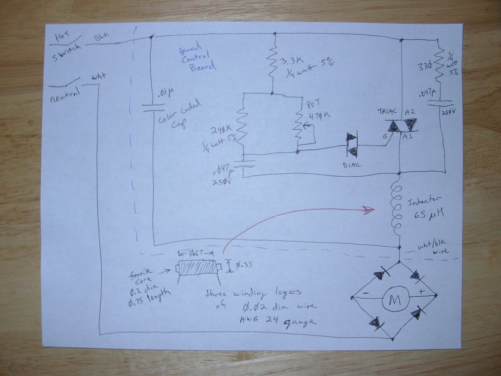
The diode diamond in the lower right is the rectifier module. Within the blue dashed box is the actual control box printed circuit board components. Black wire in, white with black wire out. Its a triac/diac circuit. Fairly standard, except for the additional components needed due to the inductive load of the DC motor (largish inductor and I think the cap with the color code). The inductor measured between 63uH and 70uH on inductance meters I have access to, so I labeled it at 65uH on the schematic. Nothing on the circuit is in the unobtainable category if anyone want to attempt to repair a fried board. You might have to rewind the inductor if it's insulation is fried, but that job shouldn't be too difficult and I wrote the dimensions down on my sketch so it could be attempted.
I'd appreciate it if anybody could double check my work, eyes aren't as good as they used to be
To fix my broken nylon potentiometer control shaft, I'm purchasing a similar potentiometer that appears to use the same shaft style and dimensions. I will then carefully open up the existing potentiometer and swap in the new shaft and discard the rest of the 75 cent new potentiometer. Then add a new knob with the standard 1/4" flat connection should result in a workable repair.
I read all 106 posts in this thread and didn't see a circuit diagram for the feed motor speed controller. I recently purchased a used 1983 M5990 planer that had its control knob broken off (among other small problems).
The control box still functions, but its rather difficult to turn the small piece of nylon shaft that still remains on my new tool.
So before taking things apart, check the forum to see what other SS owners have done. And sure enough the control box is a topic of discussion here
I have the other style of DC motor speed controller, same as dusty posted here on page 8 of this thread. Here is a photo of the start of the breakdown process of my box:
This speed controller has a few more small parts than tdubnik's fried controller. What's the difference? I think the answer is that I have the original Mark V regular planer on an upgraded power stand, and tdubnik has an actual Pro Planer. There is a small difference in speed selection between the Pro Planer and the regular planer. The circuits are very similar however.
Having said that, here is the schematic diagram (sketch really) for my control box:
The diode diamond in the lower right is the rectifier module. Within the blue dashed box is the actual control box printed circuit board components. Black wire in, white with black wire out. Its a triac/diac circuit. Fairly standard, except for the additional components needed due to the inductive load of the DC motor (largish inductor and I think the cap with the color code). The inductor measured between 63uH and 70uH on inductance meters I have access to, so I labeled it at 65uH on the schematic. Nothing on the circuit is in the unobtainable category if anyone want to attempt to repair a fried board. You might have to rewind the inductor if it's insulation is fried, but that job shouldn't be too difficult and I wrote the dimensions down on my sketch so it could be attempted.
I'd appreciate it if anybody could double check my work, eyes aren't as good as they used to be
To fix my broken nylon potentiometer control shaft, I'm purchasing a similar potentiometer that appears to use the same shaft style and dimensions. I will then carefully open up the existing potentiometer and swap in the new shaft and discard the rest of the 75 cent new potentiometer. Then add a new knob with the standard 1/4" flat connection should result in a workable repair.
-
JPG

- Platinum Member
- Posts: 34644
- Joined: Wed Dec 10, 2008 7:42 pm
- Location: Lexington, Ky (TAMECAT territory)
Re: Pro Planer speed control box problem
Determine the resistance 'taper' of the original so As to match that 'detail'.
Taper = shaft(knob) position vs resistance % of total resistance.
Taper = shaft(knob) position vs resistance % of total resistance.
╔═══╗
╟JPG ╢
╚═══╝
Goldie(Bought New SN 377425)/4" jointer/6" beltsander/12" planer/stripsander/bandsaw/powerstation /Scroll saw/Jig saw /Craftsman 10" ras/Craftsman 6" thicknessplaner/ Dayton10"tablesaw(restoredfromneighborstrashpile)/ Mark VII restoration in 'progress'/ 10E[/size](SN E3779) restoration in progress, a 510 on the back burner and a growing pile of items to be eventually returned to useful life. - aka Red Grange
-
dj1960gold
- Silver Member
- Posts: 17
- Joined: Wed Mar 26, 2014 11:34 pm
- Location: Denver Colorado
Re: Pro Planer speed control box problem
JPG wrote:Determine the resistance 'taper' of the original so As to match that 'detail'.
Taper = shaft(knob) position vs resistance % of total resistance.
My speed control potentiometer is linear taper, the half way point is 50% of total resistance. I would have been surprised if it wasn't, but its a good point to check as the housing of this potentiometer could be custom for Shop Smith and this application.
Which brings up an important point I didn't mention in the schematic diagram post:
If you look closely at the traces on the Printed Circuit Boards posted earlier in this thread (both of them), you will notice that the AC hot side wire (black) is connected to the housing of the potentiometer! Then another leg of the potentiometer housing is connected to the Triac. The trace is not directly linked between those two points on the PCB itself.
Why is that? Well I asked some guys at work who are closer to retirement than I am about this configuration, as I've never encountered this before, and the consensus is that the potentiometer housing is being used as an additional heat sink for the Triac.
The Triac (the three terminal device that looks like a transistor) is attached to a smallish heat sink by a rivet. That small heat sink was probably not enough on its own for worst case operation, so the housing of the potentiometer is also thermally connected via the traces to dissipate some heat.
So, that means the potentiometer housing is a potential shock hazard!!
It also means that just replacing the pot with an off the shelf replacement could limit the heat sinking, and/or break the hot connection if the trace wasn't also manually jumpered across the board.
In any case, the taper of the original potentiometer (or the housing) is not what I'll be replacing in this evil scheme to repair my speed control.
I'm trying to replace just the shaft which is the right most part in this photo of the potentiometer guts:
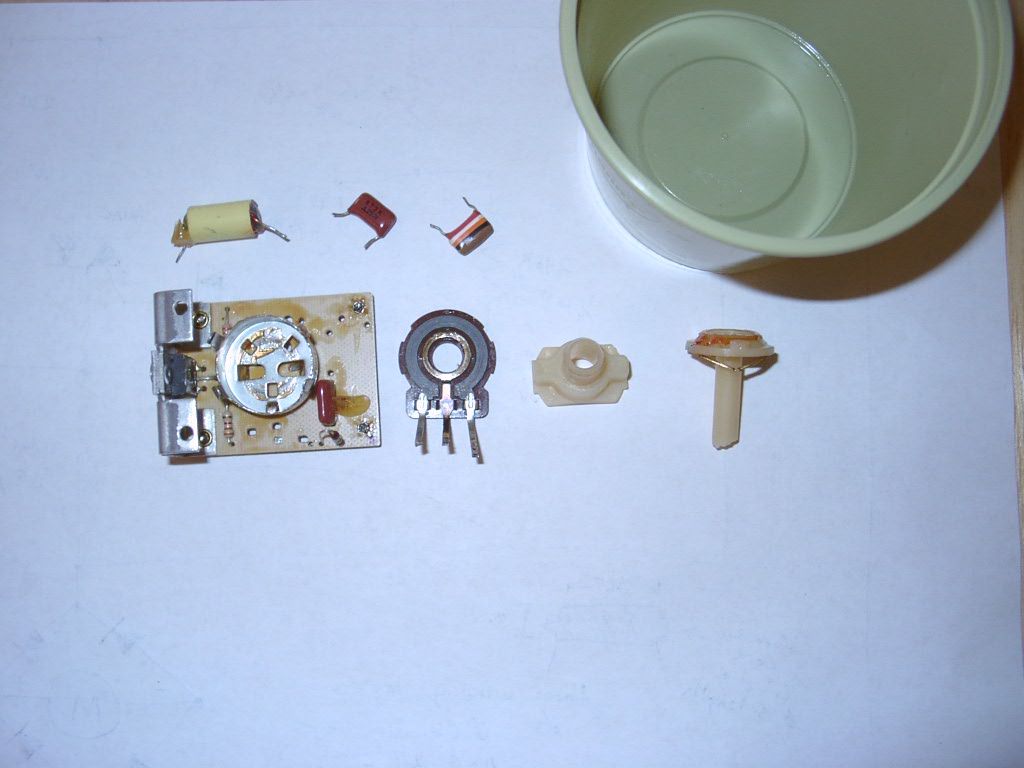
The resistive element and the housing will be reused if all goes well when the replacement potentiometer arrives in about a week.
-
JPG
- Platinum Member
- Posts: 34644
- Joined: Wed Dec 10, 2008 7:42 pm
- Location: Lexington, Ky (TAMECAT territory)
Re: Pro Planer speed control box problem
You got it under control! 
╔═══╗
╟JPG ╢
╚═══╝
Goldie(Bought New SN 377425)/4" jointer/6" beltsander/12" planer/stripsander/bandsaw/powerstation /Scroll saw/Jig saw /Craftsman 10" ras/Craftsman 6" thicknessplaner/ Dayton10"tablesaw(restoredfromneighborstrashpile)/ Mark VII restoration in 'progress'/ 10E[/size](SN E3779) restoration in progress, a 510 on the back burner and a growing pile of items to be eventually returned to useful life. - aka Red Grange
╟JPG ╢
╚═══╝
Goldie(Bought New SN 377425)/4" jointer/6" beltsander/12" planer/stripsander/bandsaw/powerstation /Scroll saw/Jig saw /Craftsman 10" ras/Craftsman 6" thicknessplaner/ Dayton10"tablesaw(restoredfromneighborstrashpile)/ Mark VII restoration in 'progress'/ 10E[/size](SN E3779) restoration in progress, a 510 on the back burner and a growing pile of items to be eventually returned to useful life. - aka Red Grange