lahola1
hi all
i'm a new member from sedona,az and 1st time shopsmith owner.
i bought a mark VII last winter ( not working; motor would only buzz, not hum)and have been reading the mark VII repair threads with great interest. with the help from these threads and comments from jpg, robinson and others i was able to get it running (bad start relay).
it runs quite well although noisier than i thought it would be (i've never been close to a shopsmith before).
but when i turn the speed up to approx 1800 rpm it tends to keep going up; sometimes to 3600,sometimes all the way up. the detent pins and springs appear to be functioning properly.
i've moved the fan sheave to 3 different positions but the speed moved the same or worse. i don't remember seeing a thrust spacer between the fan sheave and the motor (i didn't see one on JPG's teardown and rebuild thread.
how do you align the motor belt without one; what are it's dim's?
are there any other known causes for this speedup (my motor belt's width is .504". i have ordered new belts for it).
lastly, thanks for all the great posts. they have been MOST helpful.
JPG
Sorry I did not show the spacer in the reassembly thread.
Here is a pix of it in the disassembly thread.
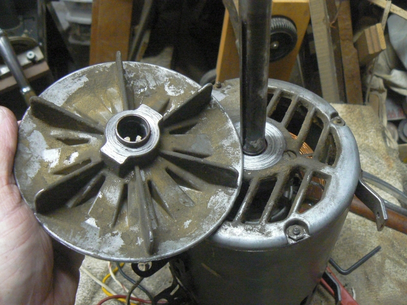
IIRC it was embeded into the sheave.
I do not recall it's dimension but I believe it was 3/16 to 1/4". I think it is the same as current MV spacer.
JPG
It is 'hidden' behind the retaining ring 'fix'.
IIRC it bears against the inner race of the bearing.(substantially into the end cap).
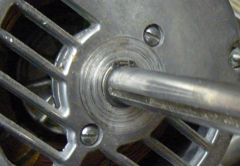
This places the fan sheave VERY close to the motor end cap.
As for the speed increasing, I feel the mark VII is prone to doing that if the detents are worn or the knob is sloppy on the shaft(the knob tilts away from the detent gizmos). Also the spring tension in the gizmos is likely weaker that original. The fix likely involves all that. I acquired a better knob. I damaged the initial knob by assembling it incorrectly(too tight and it caused the detents to become 'grooved'). Also the original knob was very sloppy on the shaft.
I have discovered that wear can make the Mark VII less than desirable and have substituted several less worn parts for those original parts that are worn.
Wish I had a magic bullet for this!
lahola1
thanks for the reply.
i will investigate my thrust spacer area more when i get my new belts.
when i 1st installed the fan sheave i had it in far enough that it would rub on the tin shield on the motor (a.o. smith btw).
luckily i have good plastic cam and gear rack.
i tried to upload pics. i don't think it worked
JPG
lahola1 wrotethanks for the reply.
i will investigate my thrust spacer area more when i get my new belts.
when i 1st installed the fan sheave i had it in far enough that it would rub on the tin shield on the motor (a.o. smith btw).
luckily i have good plastic cam and gear rack.
i tried to upload pics. i don't think it worked
You likely need 'the fix' as well.
lahola1
i don't know a whole bunch about belts and pulleys and less about expanding and contracting sheaves but i know belts and pulleys should be in alignment.
if the motor and idler sheaves expand and contract in opposite directions wouldn't that put them out of alignment all the time except the initial setup position.
if that's true by design wouldn't it be best to be in alignment at the highest speed and most out of align at the slowest speed?
or am i missing something in the design?
as i said i'm new to shopsmiths.
jsburger
lahola1 wrotei don't know a whole bunch about belts and pulleys and less about expanding and contracting sheaves but i know belts and pulleys should be in alignment.
if the motor and idler sheaves expand and contract in opposite directions wouldn't that put them out of alignment all the time except the initial setup position.
if that's true by design wouldn't it be best to be in alignment at the highest speed and most out of align at the slowest speed?
or am i missing something in the design?
as i said i'm new to shopsmiths.
The expansion and contraction does not in any way change alignment. What it does do is effectively make one pulley larger in diameter and the other one smaller in diameter. The alignment remains the same. As one gets larger the other one gets smaller thus changing the diameters in opposite directions. The effect is a change in the rotational speed (RPM) of the quill spindle. The ratio of the diameters of the two pulleys determines the RPM.
lahola1
yes, your right now that i think about it more.
thanks for straightening my thinking out before i get too far onto left field.
JPG
At slow, the floating sheave(on the motor shaft) is positioned open placing the belt deep within the pulley resulting in the belt 'center' being away from the motor/quill shaft end of the headstock.
At that setting the control sheave is positioned closed placing the belt center again(still) away from the quill end of the headstock.
As the control sheave is opened(changing speed towards fast) the belt moves towards the quill end of the headstock.
The floating sheave will react by closing causing the belt there to also move towards the quill end of the headstock.
Thus the belt is always in alignment with both pulleys.
The slope of the interior sides of the pulley sheaves is the same on both pulleys.
The position of the motor pulley fixed sheave is essentially the same as the position of the idler pulley movable control sheave when the speed is set to fast.
The position of the motor pulley movable floating sheave is essentially the same as the position of the idler pulley fixed sheave when the speed is set to slow.
A lot to digest, but that is the way it is. ;)
lahola1
yes, i see that now.
somehow i knew that my thinking was wrong; i knew a flawed design would not last since the '50's but my thought pattern couldn't get past the 2 opposite movable sheaves not equaling an offset belt.
thanks for clearification.
jerryricht
I am a new member, and arguably the owner of the best model of ShopSmith .. a free one!
My Mk VII is also humming instead of running, and I am currently in the process of replacing the bearings, replacing all of the leads because of severely cracked insulation, and replacing the external start switch. (A.O. Smith with external start switch)
First, a BIG THANKS to Everett Davis for the restored MK VII Manual! I confess I know nothing about Mk VII's and would be at a total loss without it.
Anyway, having just disassembled my motor I noticed an obvious difference from the picture that was provided.
There is no way the C Clip retainer ring should be external to the motor housing!
The front bearing has C clip retainer rings on both sides of the bearing. There is also one ring retainer on the internal side of the back bearing.
There is no way the motor shaft could migrate forward to the extent that it has in this picture without BOTH of those other retainer rings missing.
I would guess someone replaced the bearings and forgot to put the retainer rings on BEFORE they pressed the bearings. Its almost impossible to put them on after the bearings are installed.
So you will probably need to pull and replace both bearings (less than 10.00 a pair)and remember to put the retainer rings on before you press the bearing on.
Of course I could be totally wrong... as I said I know nothing compared to you guys.
JPG
The most likely cause of humming instead of running is the power switch. It controls the polarity of the start circuit.
The start relay is not likely a contributor to the problem(albeit possible).
I would suggest by passing the power switch by directly connecting the motor leads. If you need details post that.
If you are referring to my placing a retaining ring 'external' to the motor housing, realize that was merely to space the fan sheave spacer to eliminate the result of the spacer digging in to the fan sheave. If not ignore this, but please explain where that comment came from. I am not familiar with the A O Smith version motor.
Please explain 'this picture'. If the one I posted a while back - see previous paragraph.
jerryricht
Thanks JPG
Yes I was referring to the retaining ring in the picture. Thanks for the explanation I did not understand that. It certainly beats replacing the sheave.
Thanks for the advice on the switch. Continuity checked out, although I understand that does not mean there is not a problem. Good idea, I will bypass the switch when I test the motor after get it back together.
I assumed it's the motor, or start relay , because it will run if manually spun although it did start easier in reverse than forward.
Switch or not, the cracked and missing insulation on the lead wires was shocking. Pun intended:)
New leads were going to have to be soldered on to the windings so the motor was disassembled to do this. Thus new bearings while at it.
I opened the start relay and found significant corrosion so I ordered a SUPCO universal relay for about 13.00 to replace.
Like anything that's over 5o years old (including me) you usually find more problem the more you look. Or, if it's not broke ...it's fixing to break..
JPG
jerryricht wroteThanks JPG
Yes I was referring to the retaining ring in the picture. Thanks for the explanation I did not understand that. It certainly beats replacing the sheave.
Thanks for the advice on the switch. Continuity checked out, although I understand that does not mean there is not a problem. Good idea, I will bypass the switch when I test the motor after get it back together.
I assumed it's the motor, or start relay , because it will run if manually spun although it did start easier in reverse than forward.
Switch or not, the cracked and missing insulation on the lead wires was shocking. Pun intended:)
New leads were going to have to be soldered on to the windings so the motor was disassembled to do this. Thus new bearings while at it.
I opened the start relay and found significant corrosion so I ordered a SUPCO universal relay for about 13.00 to replace.
Like anything that's over 5o years old (including me) you usually find more problem the more you look. Or, if it's not broke ...it's fixing to break..
Do NOT throw the 'corroded relay' in the trash - you might need it later(when 'universal SUPCO' proves to not be a solution.
lahola1
I finally took my fan sheave offto look for a spacer on the motor shaft (ao smith).
I have no snap ring; I have no spacer. I see in the parts manual there is a different p/n for ao smith and ge motors.
so I set my space between fan sheave hub and motor cover to approx, .170". hope that's close enough.
I finally got my new idler shaft bearings and belts. I put in the same motor belt a JPG.
runs good but tach says 1030 rpm when set at 700; 6000 rpm @4500.
motor belt is up to approx .150" of the od of the idler sheaves.
I'll do more investigating tomorrow.
lahola1
btw JPG, do you think that the supco relay may not work for long? are there parts to rebuild the original one? mine was somewhat fried.
lahola1
jerryricht :
my motor problem WAS the start relay.
mine would buzz, not hum.
mine motor would not start if i spun the motor by hand.
hope this helps.
jerryricht
Thanks lahola and jpg.
BTW, I measured my spacer at .89 inches slightly more than 7/8th.
JPGs comment made me curious, the contacts in the SUPCO are not nearly as robust. So yes I will keep the old relay
However it does have a auto disconnect and auto reset to protect those old start windings. We will see how long it lasts. It may be worth replaceing occasionally than sourcing and buying another motor.
lahola1
jerryricht:
so your saying with your spacer, your fan sheave hub is a full 7/8" away from the motor cover?
JPG
lahola1 wrotejerryricht:
so your saying with your spacer, your fan sheave hub is a full 7/8" away from the motor cover?
IIRC, the spacer butts up against the inner race of the bearing(mostly inside the outer surface of the motor housing). The fan sheave to motor housing is very small(< 1/8"). I assume the difference in spacer is because of different positioning of the bearing.
