I was going to include this in my restoration thread http://www.shopsmith.net/forums/showthread.htm?t=3078 but decided to make it a stand alone thread to make it easier for a relevant search.
A VERY important inspection step when restoring an older Mark 5 is verifying that the clutch on the “Gilmer” drive system is working properly. For those of you not familiar with the “Gilmer” drive system, it was designed into the ShopSmith’s built in the mid '50s. This drive system was replaced by the much improved poly-v drive system currently used. I'm sure someone more knowledgeable will give the exact date of the switch. I believe it was late '50's??
I am in the process of overhauling my clutch on the Gilmer drive system. (parts replaced by the current #55 and 56 drive system on the headstock exploded view http://www.shopsmith.com/ownersite/prod ... 0_1_14.pdf
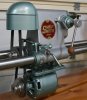
Anyway, here's some pics of the disassemble process to get to the clutch system. The clutch is designed to prevent damage to the teeth on the inside of the Gilmer drive belt in the event of a catastrophic jam where the headstock abruptly stops turning (like during a lathe operation should a tool guard ram into the workpiece.) It’s an interesting design and thanks to guidance and instruction from Bill Mayo, I decided that since I am going to keep this drive system instead of upgrading to the poly-v system, it is best to ensure that it is operating correctly.
[ATTACH]3492[/ATTACH]
[ATTACH]3493[/ATTACH]
[ATTACH]3494[/ATTACH]
[ATTACH]3495[/ATTACH]
[ATTACH]3496[/ATTACH]
[ATTACH]3497[/ATTACH]
I have to continue this on a new post. Your only allowed 5 pictures per post and I have more to show.
Gilmer Drive System - Cleaning, inspecting, testing
Moderators: HopefulSSer, admin
-
mickyd
- Platinum Member
- Posts: 2999
- Joined: Mon Feb 09, 2009 1:18 pm
- Location: San Diego, CA
- Contact:
Gilmer Drive System - Cleaning, inspecting, testing
- Attachments
-
- Img_4886mod.jpg (59.97 KiB) Viewed 13449 times
-
- Img_5020mod.jpg (66.19 KiB) Viewed 13406 times
-
- Img_5022mod.jpg (35.93 KiB) Viewed 13388 times
-
- Img_5024mod.jpg (34.96 KiB) Viewed 13404 times
-
- Img_5028mod.jpg (68.9 KiB) Viewed 13384 times
Mike
Sunny San Diego
Sunny San Diego
-
mickyd
- Platinum Member
- Posts: 2999
- Joined: Mon Feb 09, 2009 1:18 pm
- Location: San Diego, CA
- Contact:
(continuation from previous post) Click here to get back to previous post
[ATTACH]3498[/ATTACH][ATTACH]3499[/ATTACH]
A properly functioning clutch should slip somewhere between 10 and 20 foot-lbs. Above that torque and it can damage the teeth on the belt. Below that torque will result in inadequate power being transmitted to the drive sleeve assembly.
The clutch is made up of a series of both thin metal plates and fiber washers. The metal plates have the internal teeth and are locked to drive shaft whereas the fiber washers have the external teeth are locked to the aluminum hub. When the torque exceeds the clutch capacity, the sandwich of plates and fiber washers will slip on each other in turn killing the power transmission from the motor to the drive sleeve.
I am at the point where I have cleaned off all the rust and gunk off the faces of both the metal plates and fiber washer and reassembled. I am making up an auxiliary hub that will be used to connect a torque wrench to the shaft to that I can test the slip torque. Should have more info and pics to share within a day or so.
P.S. Here's my shop supervisor. She keeps an eye on me all the time as I work!!!!
[ATTACH]3500[/ATTACH]
- Attachments
-
- Img_5032mod2.jpg (20.93 KiB) Viewed 13430 times
-
- Img_5032mod1.jpg (12.82 KiB) Viewed 13429 times
-
- Img_4951mod.jpg (40.09 KiB) Viewed 13415 times
Mike
Sunny San Diego
Sunny San Diego
-
robinson46176

- Platinum Member
- Posts: 4182
- Joined: Mon Mar 09, 2009 9:00 pm
- Location: Central Indiana (Shelbyville)
Great string of pictures and info.
Is the dog a Gilmer drive too?
Is the dog a Gilmer drive too?
--
farmer
Francis Robinson
I did not equip with Shopsmiths in spite of the setups but because of them.
1 1988 - Mark V 510 (bought new), 4 Poly vee 1 1/8th HP Mark V's, Mark VII, 1 Mark V Mini, 1 Frankensmith, 1 10-ER, 1 Mark V Push-me-Pull-me Drillpress, SS bandsaw, belt sander, jointer, jigsaw, shaper attach, mortising attach, TS-3650 Rigid tablesaw, RAS, 6" long bed jointer, Foley/Belsaw Planer/molder/ripsaw, 1" sander, oscillating spindle/belt sander, Scroll saw, Woodmizer sawmill
-
JPG

- Platinum Member
- Posts: 34632
- Joined: Wed Dec 10, 2008 7:42 pm
- Location: Lexington, Ky (TAMECAT territory)
RE: Your grandfather's Hammer. Beauty is in the eyes of the Beholder!:Drobinson46176 wrote:Great string of pictures and info.
Is the dog a Gilmer drive too?
MICKYD >>>>>>>>>>>>GREAT PIX! You be doing a GREAT SERVICE to us all!:)
╔═══╗
╟JPG ╢
╚═══╝
Goldie(Bought New SN 377425)/4" jointer/6" beltsander/12" planer/stripsander/bandsaw/powerstation /Scroll saw/Jig saw /Craftsman 10" ras/Craftsman 6" thicknessplaner/ Dayton10"tablesaw(restoredfromneighborstrashpile)/ Mark VII restoration in 'progress'/ 10E[/size](SN E3779) restoration in progress, a 510 on the back burner and a growing pile of items to be eventually returned to useful life. - aka Red Grange
-
mickyd
- Platinum Member
- Posts: 2999
- Joined: Mon Feb 09, 2009 1:18 pm
- Location: San Diego, CA
- Contact:
Got my Gilmer clutch cleaned, reassembled, and torque tested last night. It tested at 16.6 ft-lbs vs. the spec Bill Mayo relayed to me of 10-20 ft-lbs. That was good news. Had it fallen out of spec, I would have had to modify "stuff".
I meant to mention in my original post that when I disassembled the clutch, I noticed that there were two metal disks and two fiber disks together instead of the expected alternating pattern of metal, fiber, metal, fiber etc. If you go back to the beginning of this thread, you'll notice it if you look closely at the close up of the disk assembly.
I had thought that someone made an error when they assembled it but Bill said he see's this on ones he's done. From an engineering standpoint, it must have been a way of LOWERING the slip torque. Instead of 7 disk to washer contact surfaces, this would have resulted in only 5. Since frictional force is a function of material, surface finish, load, and surface area, this is the only logical conclusion I can come to. Anyway, when I reassembled the clutch, I DIDN'T reassemble it like that. I did the alternating disk, washer, disk, washer pattern. My main reason for doing it that was was.....it made me feel better. Had the torque test failed, I would have put it back the original way just to see how it tested out. I kind of wish I had a spare drive to play around with just to see how changing things effect torque.
Here's what one of the metal disks and fiber washers looked like before cleaning.
[ATTACH]3526[/ATTACH]
To remove the rust off the metal disk, I used a 8" brass brush on my bench grinder. Then, to get the surface back close to what it originally would have been, I sanded progressively from 60 grit up through 1200 grit. (60, 150, 220, 400, 600, 1000, and finally 1200). For the fiber washer, I sanded lightly with 400 grit. Got so anxious to reassemble that I forgot to take after photos.
Here is my set up for the actual torque test. The nut that you see is a 5/8" heavy head hex head nut with the threads drill out so that it would fit on the Gilmer drive shaft. I drilled and tapped a 5/16-18 UNC hole for a set screw so that I could get a socket over it for torque testing.
[ATTACH]3522[/ATTACH] [ATTACH]3523[/ATTACH]
[ATTACH]3524[/ATTACH] [ATTACH]3525[/ATTACH]
So now, I just need to put the 2 new bearings back on it and it's ready to go.
I meant to mention in my original post that when I disassembled the clutch, I noticed that there were two metal disks and two fiber disks together instead of the expected alternating pattern of metal, fiber, metal, fiber etc. If you go back to the beginning of this thread, you'll notice it if you look closely at the close up of the disk assembly.
I had thought that someone made an error when they assembled it but Bill said he see's this on ones he's done. From an engineering standpoint, it must have been a way of LOWERING the slip torque. Instead of 7 disk to washer contact surfaces, this would have resulted in only 5. Since frictional force is a function of material, surface finish, load, and surface area, this is the only logical conclusion I can come to. Anyway, when I reassembled the clutch, I DIDN'T reassemble it like that. I did the alternating disk, washer, disk, washer pattern. My main reason for doing it that was was.....it made me feel better.
Here's what one of the metal disks and fiber washers looked like before cleaning.
[ATTACH]3526[/ATTACH]
To remove the rust off the metal disk, I used a 8" brass brush on my bench grinder. Then, to get the surface back close to what it originally would have been, I sanded progressively from 60 grit up through 1200 grit. (60, 150, 220, 400, 600, 1000, and finally 1200). For the fiber washer, I sanded lightly with 400 grit. Got so anxious to reassemble that I forgot to take after photos.
Here is my set up for the actual torque test. The nut that you see is a 5/8" heavy head hex head nut with the threads drill out so that it would fit on the Gilmer drive shaft. I drilled and tapped a 5/16-18 UNC hole for a set screw so that I could get a socket over it for torque testing.
[ATTACH]3522[/ATTACH] [ATTACH]3523[/ATTACH]
[ATTACH]3524[/ATTACH] [ATTACH]3525[/ATTACH]
So now, I just need to put the 2 new bearings back on it and it's ready to go.
- Attachments
-
- Img_5063mod.jpg (13.85 KiB) Viewed 13406 times
-
- Img_5065mod.jpg (12.35 KiB) Viewed 13390 times
-
- Img_5066mod.jpg (11.24 KiB) Viewed 13382 times
-
- Img_5068mod.jpg (12.94 KiB) Viewed 13402 times
-
- Img_5030mod.jpg (49.48 KiB) Viewed 13376 times
Mike
Sunny San Diego
Sunny San Diego
-
JPG
- Platinum Member
- Posts: 34632
- Joined: Wed Dec 10, 2008 7:42 pm
- Location: Lexington, Ky (TAMECAT territory)
Me thinks the 'original' sequence would have resulted in a release torque closer to 10#. Also perhaps the spring has lost some of its strength. Fibre surface finish could also be different.mickyd wrote:Got my Gilmer clutch cleaned, reassembled, and torque tested last night. It tested at 16.6 ft-lbs vs. the spec Bill Mayo relayed to me of 10-20 ft-lbs. That was good news. Had it fallen out of spec, I would have had to modify "stuff".
I meant to mention in my original post that when I disassembled the clutch, I noticed that there were two metal disks and two fiber disks together instead of the expected alternating pattern of metal, fiber, metal, fiber etc. If you go back to the beginning of this thread, you'll notice it if you look closely at the close up of the disk assembly.
I had thought that someone made an error when they assembled it but Bill said he see's this on ones he's done. From an engineering standpoint, it must have been a way of LOWERING the slip torque. Instead of 7 disk to washer contact surfaces, this would have resulted in only 5. Since frictional force is a function of material, surface finish, load, and surface area, this is the only logical conclusion I can come to. Anyway, when I reassembled the clutch, I DIDN'T reassemble it like that. I did the alternating disk, washer, disk, washer pattern. My main reason for doing it that was was.....it made me feel better.
Here's what one of the metal disks and fiber washers looked like before cleaning.
[ATTACH]3526[/ATTACH]
To remove the rust off the metal disk, I used a 8" brass brush on my bench grinder. Then, to get the surface back close to what it originally would have been, I sanded progressively from 60 grit up through 1200 grit. (60, 150, 220, 400, 600, 1000, and finally 1200). For the fiber washer, I sanded lightly with 400 grit. Got so anxious to reassemble that I forgot to take after photos.
Here is my set up for the actual torque test.
[ATTACH]3522[/ATTACH] [ATTACH]3523[/ATTACH]
[ATTACH]3524[/ATTACH] [ATTACH]3525[/ATTACH]
So now, I just need to put the 2 new bearings back on it and it's ready to go.
KEEP UP THE EXCELLENT WORK/DOCUMENTATION!!!!!:)
╔═══╗
╟JPG ╢
╚═══╝
Goldie(Bought New SN 377425)/4" jointer/6" beltsander/12" planer/stripsander/bandsaw/powerstation /Scroll saw/Jig saw /Craftsman 10" ras/Craftsman 6" thicknessplaner/ Dayton10"tablesaw(restoredfromneighborstrashpile)/ Mark VII restoration in 'progress'/ 10E[/size](SN E3779) restoration in progress, a 510 on the back burner and a growing pile of items to be eventually returned to useful life. - aka Red Grange
╟JPG ╢
╚═══╝
Goldie(Bought New SN 377425)/4" jointer/6" beltsander/12" planer/stripsander/bandsaw/powerstation /Scroll saw/Jig saw /Craftsman 10" ras/Craftsman 6" thicknessplaner/ Dayton10"tablesaw(restoredfromneighborstrashpile)/ Mark VII restoration in 'progress'/ 10E[/size](SN E3779) restoration in progress, a 510 on the back burner and a growing pile of items to be eventually returned to useful life. - aka Red Grange
-
mickyd
- Platinum Member
- Posts: 2999
- Joined: Mon Feb 09, 2009 1:18 pm
- Location: San Diego, CA
- Contact:
"Me thinks" number would actually be 12 ft-lbs but technically, I have to agree with what you said".....closer to 10#."
Me thinks number comes from:
If 7 disk surfaces results in 16.6 ft-lbs then 1 disk surface give 2.4 ft-lbs (assumes the beast is linear) SO, 5 disk surfaces would give you 5 x 2.4ft-lbs = 12 ft-lbs.
If I had a spare, I'd be 'sperimenting.
Whatta ya think?
Your right about the spring tension and fiber surface. Even after sanding it with 400 grit, it still had a glazed appearance. I was hesitant to sand it too much just it case it made it too course, resulting in higher torque. I figured that it would be a bear to get the surface finish of the fiber disk tweeked in so I didn't want to mess with it too much.
Mike
Sunny San Diego
Sunny San Diego
-
JPG
- Platinum Member
- Posts: 34632
- Joined: Wed Dec 10, 2008 7:42 pm
- Location: Lexington, Ky (TAMECAT territory)
Me thinks your math/thinking is right on!:Dmickyd wrote:"Me thinks" number would actually be 12 ft-lbs but technically, I have to agree with what you said".....closer to 10#."
Me thinks number comes from:
If 7 disk surfaces results in 16.6 ft-lbs then 1 disk surface give 2.4 ft-lbs (assumes the beast is linear) SO, 5 disk surfaces would give you 5 x 2.4ft-lbs = 12 ft-lbs.
If I had a spare, I'd be 'sperimenting.
Whatta ya think?
╔═══╗
╟JPG ╢
╚═══╝
Goldie(Bought New SN 377425)/4" jointer/6" beltsander/12" planer/stripsander/bandsaw/powerstation /Scroll saw/Jig saw /Craftsman 10" ras/Craftsman 6" thicknessplaner/ Dayton10"tablesaw(restoredfromneighborstrashpile)/ Mark VII restoration in 'progress'/ 10E[/size](SN E3779) restoration in progress, a 510 on the back burner and a growing pile of items to be eventually returned to useful life. - aka Red Grange
╟JPG ╢
╚═══╝
Goldie(Bought New SN 377425)/4" jointer/6" beltsander/12" planer/stripsander/bandsaw/powerstation /Scroll saw/Jig saw /Craftsman 10" ras/Craftsman 6" thicknessplaner/ Dayton10"tablesaw(restoredfromneighborstrashpile)/ Mark VII restoration in 'progress'/ 10E[/size](SN E3779) restoration in progress, a 510 on the back burner and a growing pile of items to be eventually returned to useful life. - aka Red Grange