update 9-16-09 - There is a pdf file of this entire repair procedure posted on this another thread. If you'd like to download that procedure, Click here .
Original post below
The chuck that came with my ER was frozen solid. Wouldn't budge.
.
.
[ATTACH]5922[/ATTACH]
.
.
I figured that I could unfreeze it with a bath in evaporust. I left it fully submerged for 3 days. Still frozen. I decided to take it out and use “Kroil”. Sprayed it down daily for week but all that did was waste the “Kroil”. Next gave it a mineral spirit bath for a week. No good. I remembered the looks of a before and after chuckthat heathicus restored so I asked him for some advise. He told me to just disassemble this thing. Had no idea how to do that but he was able to explain and provide a couple links that described it. Their discussion was pretty good but the photos were real weak.
Here’s the process I used to get my chuck freed up. Thanks again to heathicus. I LOVE tackling first time projects.
Before you press the sleeve off, scribe a line with a razor blade to show where the original sleeve position is. This reference line is needed when you press the sleeve back on to ensure that the spacing of the key pilot hole to the teeth on the sleeve is maintained.
.
.
[ATTACH]5923[/ATTACH]
.
.
Used my bearing puller to get the outer sleeve up over the jaw end exposing the guts. Prior to removing the sleeve, they recommend that the jaws be anywhere from half and fully closed. Fortunately, mine was frozen at about the halfway point.
.
.
[ATTACH]5924[/ATTACH]. . .[ATTACH]5925[/ATTACH]
.
.
With the sleeve removed, you can see that it was pretty messy inside. No wonder the soak methods I used didn’t work.
.
.
[ATTACH]5927[/ATTACH]
Post continued<<<< CLICK ON THIS TO CONTINUE (if you came here and the page appears as a single post) or just continue scrolling to the next post or going to the next page
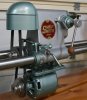
Restoration Progress On My 1952 ER10
Moderator: admin
-
mickyd
- Platinum Member
- Posts: 2999
- Joined: Mon Feb 09, 2009 1:18 pm
- Location: San Diego, CA
- Contact:
Repairing frozen Jacobs chuck
- Attachments
-
- Img_5368mod1.jpg (47.82 KiB) Viewed 25141 times
-
- Img_6859mod.jpg (40.81 KiB) Viewed 25113 times
-
- Hpim0546mod.jpg (65.83 KiB) Viewed 25117 times
-
- Hpim0550mod.jpg (68.97 KiB) Viewed 25104 times
-
- Hpim0555mod.jpg (77.42 KiB) Viewed 25102 times
Mike
Sunny San Diego
Sunny San Diego
-
mickyd
- Platinum Member
- Posts: 2999
- Joined: Mon Feb 09, 2009 1:18 pm
- Location: San Diego, CA
- Contact:
Click here to open the previous post as a single page or just scroll up to see previous post
.
.
Once the sleeve was off, the next step was to remove the split nut. The split nut is what actually moves the jaws in and out as the sleeve is rotated. FYI - The sleeve is held in place only by the press-fit contact of the split nut inside the sleeve
.
.
[ATTACH]5928[/ATTACH]
.
.
Once the split nut is removed, it exposes the threaded ends of the jaws. To remove the jaws, you first need to push two of the three jaws toward the backside of the chuck as shown. On mine, the jaws were frozen in their mating holes so I have to use a persuader to gently tap the tips of 2 jaws backwards.
.
.
[ATTACH]5939[/ATTACH]
.
.
Once the 2 jaws are pushed back you then pull the third forward and out of the hole that it rides in. Once out, you have to make sure that you identify what jaw came out of what hole. Since I couldn't’t find any markings on my chuck body or the jaw itself, I numbered both the jaw and mating hole with a magic marker.
.
.
[ATTACH]5930[/ATTACH]
.
.
Each jaw is machined differently at the base of the teeth.
.
.
[ATTACH]5931[/ATTACH]
.
.
Once fully disassembled, all parts were cleaned with mineral spirits than brass wire brushed on the bench grinder. The holes that the jaws ride in were cleaned with cotton swabs. Here’s all the components cleaned up.
.
.
[ATTACH]5932[/ATTACH]
Post continued<<<< CLICK ON THIS TO CONTINUE (if you came here and the page appears as a single post) or just continue scrolling to the next post or going to the next page
.
.
Once the sleeve was off, the next step was to remove the split nut. The split nut is what actually moves the jaws in and out as the sleeve is rotated. FYI - The sleeve is held in place only by the press-fit contact of the split nut inside the sleeve
.
.
[ATTACH]5928[/ATTACH]
.
.
Once the split nut is removed, it exposes the threaded ends of the jaws. To remove the jaws, you first need to push two of the three jaws toward the backside of the chuck as shown. On mine, the jaws were frozen in their mating holes so I have to use a persuader to gently tap the tips of 2 jaws backwards.
.
.
[ATTACH]5939[/ATTACH]
.
.
Once the 2 jaws are pushed back you then pull the third forward and out of the hole that it rides in. Once out, you have to make sure that you identify what jaw came out of what hole. Since I couldn't’t find any markings on my chuck body or the jaw itself, I numbered both the jaw and mating hole with a magic marker.
.
.
[ATTACH]5930[/ATTACH]
.
.
Each jaw is machined differently at the base of the teeth.
.
.
[ATTACH]5931[/ATTACH]
.
.
Once fully disassembled, all parts were cleaned with mineral spirits than brass wire brushed on the bench grinder. The holes that the jaws ride in were cleaned with cotton swabs. Here’s all the components cleaned up.
.
.
[ATTACH]5932[/ATTACH]
Post continued<<<< CLICK ON THIS TO CONTINUE (if you came here and the page appears as a single post) or just continue scrolling to the next post or going to the next page
- Attachments
-
- Hpim0561mod.jpg (79.07 KiB) Viewed 24952 times
-
- Hpim0568mod.jpg (116.08 KiB) Viewed 24966 times
-
- Hpim0570mod.jpg (41.49 KiB) Viewed 24953 times
-
- Hpim0576mod.jpg (62.7 KiB) Viewed 24968 times
-
- Hpim0564mod.jpg (107.67 KiB) Viewed 24935 times
Mike
Sunny San Diego
Sunny San Diego
-
mickyd
- Platinum Member
- Posts: 2999
- Joined: Mon Feb 09, 2009 1:18 pm
- Location: San Diego, CA
- Contact:
Click here to open the previous post as a single page or just scroll up to see the previous post
.
.
Before reassembling, grease each of the 3 jaw teeth and also the threads inside the split ring.
.
.
[ATTACH]5933[/ATTACH]
.
.
Next was the reassembly. Put all 3 jaws into their respective mating holes. It’s critical that they go back in the same holes they originally came out of. Once in, you want to extend them until the tips are touching each other EQUALLY. The ends have to be flush. This is done by getting them close to full extension then alternate pushing each one just a little bit until they contact equally.
.
.
[ATTACH]5934[/ATTACH]
.
.
Next the split nut is placed into its’ slot so that the teeth of the jaws engage into the female thread of the nut. Notice that there is a correct direction to reinstall the split nut as seen by the angle of the thread going in the same direction as the jaw thread. The instruction said that you might have to “jimmie” the nut a little to get the teeth to mess. Mine went on first shot….no jimmie needed.
.
.
[ATTACH]5935[/ATTACH]
.
.
Once both split nut halves are installed, press the sleeve back in place. It goes over the jaws and gets pressed toward the back of the chuck. You have to stop pressing when it gets to the same original position.
.
.
[ATTACH]5936[/ATTACH]
.
.
.
REMEMBER--as mentioned previously, the sleeve is held in place only by the press-fit contact of the split nut inside the sleeve. When you rotate the sleeve, it in turn rotates the split nut and moves the jaws either in or out. - Until I did this repair, I never knew exactly how the chuck functioned. Engineering masterpiece if you ask me!!
.
.
.
.
.
.
.
VOILA...a smooth acting chuck!!
.
.
[ATTACH]5944[/ATTACH]
.
.
Before reassembling, grease each of the 3 jaw teeth and also the threads inside the split ring.
.
.
[ATTACH]5933[/ATTACH]
.
.
Next was the reassembly. Put all 3 jaws into their respective mating holes. It’s critical that they go back in the same holes they originally came out of. Once in, you want to extend them until the tips are touching each other EQUALLY. The ends have to be flush. This is done by getting them close to full extension then alternate pushing each one just a little bit until they contact equally.
.
.
[ATTACH]5934[/ATTACH]
.
.
Next the split nut is placed into its’ slot so that the teeth of the jaws engage into the female thread of the nut. Notice that there is a correct direction to reinstall the split nut as seen by the angle of the thread going in the same direction as the jaw thread. The instruction said that you might have to “jimmie” the nut a little to get the teeth to mess. Mine went on first shot….no jimmie needed.
.
.
[ATTACH]5935[/ATTACH]
.
.
Once both split nut halves are installed, press the sleeve back in place. It goes over the jaws and gets pressed toward the back of the chuck. You have to stop pressing when it gets to the same original position.
.
.
[ATTACH]5936[/ATTACH]
.
.
.
REMEMBER--as mentioned previously, the sleeve is held in place only by the press-fit contact of the split nut inside the sleeve. When you rotate the sleeve, it in turn rotates the split nut and moves the jaws either in or out. - Until I did this repair, I never knew exactly how the chuck functioned. Engineering masterpiece if you ask me!!
.
.
.
.
.
.
.
VOILA...a smooth acting chuck!!
.
.
[ATTACH]5944[/ATTACH]
- Attachments
-
- Hpim0579mod.jpg (88.12 KiB) Viewed 24790 times
-
- Hpim0581mod.jpg (66.85 KiB) Viewed 24786 times
-
- Hpim0583mod.jpg (84.09 KiB) Viewed 24781 times
-
- Hpim0585mod.jpg (62.3 KiB) Viewed 24770 times
-
- Img_5368mod3jpg.jpg (89.88 KiB) Viewed 24771 times
Mike
Sunny San Diego
Sunny San Diego
-
JPG

- Platinum Member
- Posts: 35451
- Joined: Wed Dec 10, 2008 7:42 pm
- Location: Lexington, Ky (TAMECAT territory)
Something is ailing with attachment 5929.
I do not think the jaw 'groove' matters as long as the jaw sequence is correct and the split nut is correctly inserted.
RE Holey Knot! After seeing how GOOD those old boards look, I agree, to 'replace them' WOULD be a sin. I vote for clear epoxy or whatever for all the reasons already stated by others. Looks like douglas fir to me, but without smelling it I cannot say for sure(it MAY be pine).
FWIW I do not understand WHY a multi-craft jacobs chuck was with the ER10. As I understand these things, it came with a jacobs 3326!
GREAT IDEA starting a new thread and linking to the relative posts in this one. Did you include all three posts? Only one existed when I 'dropped in here'.
mickyd wrote:Once the sleeve was off, the next step was to remove the split nut. The split nut is what actually moves the jaws in and out as the sleeve is rotated. The sleeve is press fit over the split nut.
.
.
[ATTACH]5928[/ATTACH]
.
.
Once the split nut is removed, it exposes the threaded ends of the jaws. To remove the jaws, you first need to push two of the three jaws toward the backside of the chuck as shown. Mine were frozen so I have to use a persuader to gently tap the 2 jaws backwards.
.
.
[ATTACH]5929[/ATTACH]
.
.
Once the 2 jaws are pushed back you then pull the third forward and out of the hole that it rides in. Once out, you have to make sure that you identify what jaw came out of what hole. Since I couldn’t find any markings on my chuck body or the jaw itself, I numbered both the jaw and mating hole with a magic marker.
.
.
[ATTACH]5930[/ATTACH]
.
.
Each jaw is machined differently at the base of the teeth.
.
.
[ATTACH]5931[/ATTACH]
.
.
Once fully disassembled, all parts were cleaned with mineral spirits than brass wire brushed on the bench grinder. The holes that the jaws ride in were cleaned with cotton swabs. Here’s all the components cleaned up.
.
.
[ATTACH]5932[/ATTACH]
Post continued
╔═══╗
╟JPG ╢
╚═══╝
Goldie(Bought New SN 377425)/4" jointer/6" beltsander/12" planer/stripsander/bandsaw/powerstation /Scroll saw/Jig saw /Craftsman 10" ras/Craftsman 6" thicknessplaner/ Dayton10"tablesaw(restoredfromneighborstrashpile)/ Mark VII restoration in 'progress'/ 10E[/size](SN E3779) restoration in progress, a 510 on the back burner and a growing pile of items to be eventually returned to useful life. - aka Red Grange
-
mickyd
- Platinum Member
- Posts: 2999
- Joined: Mon Feb 09, 2009 1:18 pm
- Location: San Diego, CA
- Contact:
Attachment 5929 fixed. I forgot that I changed it after I uploaded and forget to reinsert it.JPG40504 wrote:Something is ailing with attachment 5929.
I do not think the jaw 'groove' matters as long as the jaw sequence is correct and the split nut is correctly inserted.
RE Holey Knot! After seeing how GOOD those old boards look, I agree, to 'replace them' WOULD be a sin. I vote for clear epoxy or whatever for all the reasons already stated by others. Looks like douglas fir to me, but without smelling it I cannot say for sure(it MAY be pine).
FWIW I do not understand WHY a multi-craft jacobs chuck was with the ER10. As I understand these things, it came with a jacobs 3326!
GREAT IDEA starting a new thread and linking to the relative posts in this one. Did you include all three posts? Only one existed when I 'dropped in here'.
Glad you came to your senses on me keeping my original bench boards, especially after my genealogy poststating that the tree who bore those babies was just a seedling at the end of the Civil War in 1865. I knew that I could get them to clean up nicely, thanks to help from sdssmith and his planer. I'm in the process of getting the black water stains out. Post on that to follow soon.
What do you mean when you say "I do not think the jaw 'groove' matters as long as the jaw sequence is correct and the split nut is correctly inserted."
RE how come a multi-craft chuck.......?????
 You mean I have non-original equipment with my $30 steal
 RE not including all three posts comment.....I did it a different way. I included a hyperlink at the end of each post #200, and 201 to get the person to the next post in the event that someone just stumbles across it in a search.
Mike
Sunny San Diego
Sunny San Diego
-
JPG
- Platinum Member
- Posts: 35451
- Joined: Wed Dec 10, 2008 7:42 pm
- Location: Lexington, Ky (TAMECAT territory)
Methinks the jaw grooves ARE identical. Jacobs refers only to their SEQUENCE in their reassembly instructions. The jaws vary in the location of the first thread valley at the jaw tip end(shoulder). They need to be arranged so that the thread is progresssive around the barrel of the chuck when viewed from the jaw tip end. Going clockwise, jaw with shortest distance from shoulder to thread first, followed by the jaws with increasing distance in sequence,
I find it hard to believe sdssmith only has one planer!
Put a link from # 201 and 202 to 200 (In case the stumbler stumbles falls into 201 or 202) ;>)
I find it hard to believe sdssmith only has one planer!
Put a link from # 201 and 202 to 200 (In case the stumbler stumbles falls into 201 or 202) ;>)
╔═══╗
╟JPG ╢
╚═══╝
Goldie(Bought New SN 377425)/4" jointer/6" beltsander/12" planer/stripsander/bandsaw/powerstation /Scroll saw/Jig saw /Craftsman 10" ras/Craftsman 6" thicknessplaner/ Dayton10"tablesaw(restoredfromneighborstrashpile)/ Mark VII restoration in 'progress'/ 10E[/size](SN E3779) restoration in progress, a 510 on the back burner and a growing pile of items to be eventually returned to useful life. - aka Red Grange
╟JPG ╢
╚═══╝
Goldie(Bought New SN 377425)/4" jointer/6" beltsander/12" planer/stripsander/bandsaw/powerstation /Scroll saw/Jig saw /Craftsman 10" ras/Craftsman 6" thicknessplaner/ Dayton10"tablesaw(restoredfromneighborstrashpile)/ Mark VII restoration in 'progress'/ 10E[/size](SN E3779) restoration in progress, a 510 on the back burner and a growing pile of items to be eventually returned to useful life. - aka Red Grange
-
mickyd
- Platinum Member
- Posts: 2999
- Joined: Mon Feb 09, 2009 1:18 pm
- Location: San Diego, CA
- Contact:
Quill bearing installation
I was able to use my bearing puller to remove the two bearings from the quill but because the quill is so long, my puller didn't have the reach to install the bearings. Instead, needed to use "universal" tools........claw hammer and 5/8" open end wrench.
First bearing to install is the one on the splined end of shaft (I'll call it rear bearing). I wasn't thinking initially and I installed the opposite side first. Problem with that is you cannot later install the rear bearing since it is located up inside the quill housing. This pic shows the mistake of installing the front bearing. It does however give you a good view of the hammer and open end wrench bearing assembly method. As long as you use caution when starting the bearing to make sute that it goes on straight, this seemed to be a pretty good method. After I installed the front bearing up tight up against the shoulder, I realized my mistake and had to use my puller to remove it before I could proceed.
.
.
[ATTACH]6071[/ATTACH]
.
.
Using the same hammer and wrench method, installed the bearing on the splined end. Once that bearing is installed tightly up against the shoulder, you butt the retaining collar up against the bearing and secure it onto the shaft with it's set screw.
.
.
[ATTACH]6072[/ATTACH]
.
.
The shaft is installed into the quill housing from the backside and the front bearing is then installed. With the front bearing installed tightly up against the shaft shoulder, the bearing still stuck out a 1/4" or so. I thought something was wrong. I picked up the quill assembly and saw that there was a a lot of forward to backward play when pulling and pushing on the shaft. I was able to slide the shaft back and forth in the quill housing 1/4". This made me question if the back bearing was still properly installed up against it's shoulder so I pressed the shaft out, removing the front bearing, and clearly saw that the back bearing WAS in the correct position so I reinstalled the front bearing.
.
.
[ATTACH]6073[/ATTACH]
.
.
I then figured out that the play is eliminated by the retaining collar contacting up against the inside suface of the gauge collar. As you recall, I broke the original gauge collar when I removed it so it gave me the chance to see the assembly as if in cross section. I was kind of glad that I could see the innards! The gauge collar isn't installed all the way in the photo so that you can see the relationship with the retaining collar.
.
.
[ATTACH]6074[/ATTACH]
.
.
With the gauge collars in it's final position, it eliminates the back and forth play in the shaft. I now see why it's called a "gauge collar" since it gauges the distance between the groove position and retaining collar. That's my logic and I'm sticking to it (yet open to discussion however).
.
.
[ATTACH]6085[/ATTACH]
.
.
.
Next to do.....reassembly motor after painting....
- Attachments
-
- IMG_7333mod.JPG (50.78 KiB) Viewed 24197 times
-
- Img_7338mod.jpg (43.01 KiB) Viewed 24193 times
-
- IMG_7346mod.JPG (77.42 KiB) Viewed 24196 times
-
- IMG_7354mod.JPG (71.86 KiB) Viewed 24197 times
-
- IMG_7351mod.JPG (70.04 KiB) Viewed 24151 times
Mike
Sunny San Diego
Sunny San Diego
-
mickyd
- Platinum Member
- Posts: 2999
- Joined: Mon Feb 09, 2009 1:18 pm
- Location: San Diego, CA
- Contact:
What a chore it was stripping all the orange paint and primer off the ER parts. I was going to just prime and paint over it. like I did on the headstock and motor, but when I washed and blew off the parts with my compressor, a few areas flaked off so I decided to strip them down to bear metal.
I had a half gallon of STRIP-X 15 minute chemical stripper that I wanted to use up vs. going with the preferred Citrustrip stripper. It had a tough time in several areas so it needed a couple coats. As it was, it still didn't cut through all the primer on a few pieces. Anyway they are done as far as I plan on doing them. They've been wire wheel brushed after stripping to remove as much primer as I could get off. Time for prime and paint. Still deciding on final paint color though.
.
[ATTACH]6369[/ATTACH]
.
I really had hoped to get the abrasive blasting processworking so that I didn't have to use paint stripper but I ran into to many roadblocks. I'm still going to work on the blasting process for future projects though.
- Attachments
-
- Img_7470mod.jpg (97.43 KiB) Viewed 23869 times
Mike
Sunny San Diego
Sunny San Diego
-
a1gutterman
- Platinum Member
- Posts: 3653
- Joined: Tue Jan 09, 2007 12:45 am
- Location: "close to" Seattle
Is that an intentional pun due to the difficulty of the job, or maybe an unintentional pun due to your subconscience realizing the difficulty of the job???mickyd wrote:What a chore it was stripping all the orange paint and primer off the ER parts. I was going to just prime and paint over it. like I did on the headstock and motor, but when I washed and blew off the parts with my compressor, a few areas flaked off so I decided to strip them down to bear metal...
Tim
Buying US made products will help keep YOUR job or retirement funds safer.
Buying US made products will help keep YOUR job or retirement funds safer.
-
mickyd
- Platinum Member
- Posts: 2999
- Joined: Mon Feb 09, 2009 1:18 pm
- Location: San Diego, CA
- Contact:
Wow....it was an unintentional pun!!! Very fitting though. I can see how the involuntary muscle response happened. You must have had a lot of "pun" typing your post.a1gutterman wrote:Is that an intentional pun due to the difficulty of the job, or maybe an unintentional pun due to your subconscience realizing the difficulty of the job???Do knot let the bare scare you away now, you here?:D
Mike
Sunny San Diego
Sunny San Diego