Paul said it true!:) Speed and light cuts.
Mike, I'm glad you got through all of your safety/technique lessons and turned out a nice looking piece. A little sanding should take off most of that burn. At least so it is not very noticeable.
mickyd's Woodworking Projects
Moderator: admin

Hi,
Don't want to take anything away from the project here but I thought maybe I could help out a little on some of the things in case someone else would like to make one of these....
First lets look at the tongue and groove joint. The way the author shows is to make two passes by flipping the wood. The bad news is that this creates a climbing cut for the second pass. This is quite easy to fix. By making an adjustment of the fence position and cutting the far side rather then the close side makes all the difference.
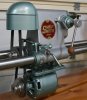
First let me say this is a jointech router table mounted out board on my shopsmith 520 using the 5 foot tubes and legs. The fence is one from oak park UHMW plastic and is clamped to the table with c-clamps (also oak park). I located the groove by using brass bars, the bit height was also set with a brass bar. This shows a close up of the set up:
[ATTACH]9568[/ATTACH]
The second pass is then made by flipping the wood. Note that the cutter is now forcing the wood towards the fence like it should.
[ATTACH]9569[/ATTACH]
I then readjusted the fence, again using a brass bar to adjust. (Do not change the height adjustment). With the bit now embedded in the fence the measurement is to the outside of the bit from the fence.
Luck or skill think what you like but it fit the first time.
[ATTACH]9570[/ATTACH]
I didn't want to take the time to do a lesson on starter pins/safety pins but so you know what they look like here is a picture. I personal used them today but then that is how I normally work. You need only start your cuts with the pin and the rest of the time you are just working off the bearing on the cutter. Keep in mind I left the parts long so I did not have to try and start at a corner or have to finish at a corner.
[ATTACH]9571[/ATTACH]
Next post I show how I did the slot...
Ed
Don't want to take anything away from the project here but I thought maybe I could help out a little on some of the things in case someone else would like to make one of these....
First lets look at the tongue and groove joint. The way the author shows is to make two passes by flipping the wood. The bad news is that this creates a climbing cut for the second pass. This is quite easy to fix. By making an adjustment of the fence position and cutting the far side rather then the close side makes all the difference.
First let me say this is a jointech router table mounted out board on my shopsmith 520 using the 5 foot tubes and legs. The fence is one from oak park UHMW plastic and is clamped to the table with c-clamps (also oak park). I located the groove by using brass bars, the bit height was also set with a brass bar. This shows a close up of the set up:
[ATTACH]9568[/ATTACH]
The second pass is then made by flipping the wood. Note that the cutter is now forcing the wood towards the fence like it should.
[ATTACH]9569[/ATTACH]
I then readjusted the fence, again using a brass bar to adjust. (Do not change the height adjustment). With the bit now embedded in the fence the measurement is to the outside of the bit from the fence.
Luck or skill think what you like but it fit the first time.
[ATTACH]9570[/ATTACH]
I didn't want to take the time to do a lesson on starter pins/safety pins but so you know what they look like here is a picture. I personal used them today but then that is how I normally work. You need only start your cuts with the pin and the rest of the time you are just working off the bearing on the cutter. Keep in mind I left the parts long so I did not have to try and start at a corner or have to finish at a corner.
[ATTACH]9571[/ATTACH]
Next post I show how I did the slot...
Ed
- Attachments
-
- DSCF8810sc.jpg (77.55 KiB) Viewed 4379 times
-
- DSCF8811sc.jpg (80.69 KiB) Viewed 4378 times
-
- DSCF8814sc.jpg (67.47 KiB) Viewed 4378 times
-
- DSCF8815sc.jpg (63.77 KiB) Viewed 4378 times
{Knight of the Shopsmith} [Hero's don't wear capes, they wear dog tags]
Hi,
Next I did the slot, first you need to adjust the fence so the bit will cut in the center of the work piece. I again used brass bars to find that location.
If I recall the author talked about using a straight bit for this operation, he was able to do that because he had drilled holes at each end. I was planning on using a spiral which can plunge and that is what is shown here. If you are going to use a straight bit you will need to drill the holes. (You really only need the starting hole).
You will need to make several passes to cut though the work piece so take your time and let the router work.
Now what I like to do for this operation is to mark reducer insert with the in and out feed sides of the bit marked. This can be done with a small square block of wood or a tool. If you look you should be able to see the marks.
I then line this up with the ends of the slots and then mark the fence where the part end starts and ends. See green tape and marks.
[ATTACH]9572[/ATTACH]
Then I line the mark up with the end of the part and lower it into the bit. With only one hand free to while attempting taking the picture the hand position isn't right but it should sort of give you the idea. Keep the part against the fence and lower it on the spinning bit then feed to the second mark and lift off. (Keep in mind the part is still over sized).
[ATTACH]9573[/ATTACH]
[ATTACH]9574[/ATTACH]
I made a couple of other changes but they are not critical. I decided to drill and add a brass insert, 10-24 as that fit a plastic knob I had and I'm not all that into making it pretty. I also went with a small magnet I had in the shop, made the hole longer and deeper then need, filled part way with epoxy and then stuck a piece of wax paper between the magnet and the ruler and placed the magnet into the epoxy to harden.
[ATTACH]9575[/ATTACH]
At this point it just needs some sanding and the brass but I don't know if I'll finish it or not... depends on how much the brass costs.
How you find this a help.
Ed
- Attachments
-
- DSCF8816sc.jpg (92.16 KiB) Viewed 4418 times
-
- DSCF8817sc.jpg (90.83 KiB) Viewed 4376 times
-
- DSCF8819sc.jpg (63.88 KiB) Viewed 4373 times
-
- DSCF8820sc.jpg (60.34 KiB) Viewed 4374 times
{Knight of the Shopsmith} [Hero's don't wear capes, they wear dog tags]
-
shipwright
- Platinum Member
- Posts: 1165
- Joined: Tue Dec 15, 2009 7:28 pm
- Location: Vancouver Island, Canada
- Contact:
Apology for not paying attention.
Sorry, Mike you must have been wondering what I was on about in this post http://www.shopsmith.net/forums/showpos ... tcount=488 when I was talking about grooves and tails and tightening. To be honest, all I looked at were your sketches and not the plans. I automatically jumped (wrongly) to the conclusion that the slide was a dovetail. I blundered on assuming that the lock was a screw that jammed the dovetail. I guess if I were making one that's how I would have done it so I just thought (wrongly, remember) that everybody would do it that way. Maybe next time I'll look more closely. .....but probably not.
Paul M
Paul M
Paul M ........ The early bird gets the worm but the second mouse gets the cheese
-
mickyd
- Platinum Member
- Posts: 2999
- Joined: Mon Feb 09, 2009 1:18 pm
- Location: San Diego, CA
- Contact:
You can post anything on any of my threads anytime. Your expertise and willingness to share your thoughts and methods are greatly appreciated. That's how we all benefit from this forum. Collective thinking and sharing makes it happen. Your post complimented this thread for sure. Thanks Ed.reible wrote:Hi,
Don't want to take anything away from the project here but I thought maybe I could help out a little on some of the things in case someone else would like to make one of these....
Ed
I'm glad that I was able to choose a project that others take an interest in for themselves. This was a great looking tool with functionality that I knew I wanted and now, you'll have one too.
When you showed how the groove can be cut without the climb cut condition by first cutting the far edge, flipping, then cutting the near edge, it sparked a memory that I had read that somewhere in the past year. Unfortunately, rookie reading vs. recall when you get to use it in an application can be less than 100%. Seeing it in application however solidifies the learning. I'll never forget now.
Can you show a pic of how you use the brass bars to set both the fence and bit height. I think I know what your talking about but would like to see for sure.
Hopefully you can locate the 3/4" and 1/4" x .064" brass strip. It's cheap. Only $2 each here in SD for a 10" long strips. I'll have extra so if you want some, just PM and address and I'd be happy to send you some. I was supposed to pick mine up today but the companies reorder didn't come in on the 3/4". Hopefully mid next week.
Thanks again for the post.
Mike
Sunny San Diego
Sunny San Diego
-
robinson46176
- Platinum Member
- Posts: 4182
- Joined: Mon Mar 09, 2009 9:00 pm
- Location: Central Indiana (Shelbyville)
mickyd wrote: I'll never forget now.
Someday you will be amazed at what you can forget...
--
farmer
Francis Robinson
I did not equip with Shopsmiths in spite of the setups but because of them.
1 1988 - Mark V 510 (bought new), 4 Poly vee 1 1/8th HP Mark V's, Mark VII, 1 Mark V Mini, 1 Frankensmith, 1 10-ER, 1 Mark V Push-me-Pull-me Drillpress, SS bandsaw, belt sander, jointer, jigsaw, shaper attach, mortising attach, TS-3650 Rigid tablesaw, RAS, 6" long bed jointer, Foley/Belsaw Planer/molder/ripsaw, 1" sander, oscillating spindle/belt sander, Scroll saw, Woodmizer sawmill
-
mickyd
- Platinum Member
- Posts: 2999
- Joined: Mon Feb 09, 2009 1:18 pm
- Location: San Diego, CA
- Contact:
Prototype artwork of my horizontal read scale on the left, scan of my favorite quality steel scale on the right.
.
.
[ATTACH]9576[/ATTACH]
.
.
Scale division lines are .005" thick. Next step is laser photocopying the artwork (minus the actual scale image) onto the Press-N-Peel transfer material then ironing it on to a scrap piece of brass that's been cleaned real well with #00 steel wool. Then peel the Press-N-Peel off leaving the black toner on the brass and throw the brass in ferric chloride acid to etch away the white areas. I think this is going to work!!! Great idea shipwright. I'll be trying this early next week.
Oh, and JPG, since I know you will notice this, the 64th increments on my scanned image of the scale are chopped off.
And farmer, you mean to tell me that you have forgotten something previously known.
.
.
[ATTACH]9576[/ATTACH]
.
.
Scale division lines are .005" thick. Next step is laser photocopying the artwork (minus the actual scale image) onto the Press-N-Peel transfer material then ironing it on to a scrap piece of brass that's been cleaned real well with #00 steel wool. Then peel the Press-N-Peel off leaving the black toner on the brass and throw the brass in ferric chloride acid to etch away the white areas. I think this is going to work!!! Great idea shipwright. I'll be trying this early next week.
Oh, and JPG, since I know you will notice this, the 64th increments on my scanned image of the scale are chopped off.
And farmer, you mean to tell me that you have forgotten something previously known.
- Attachments
-
- scale1200i nch rule moe.jpg (60.16 KiB) Viewed 4413 times
Mike
Sunny San Diego
Sunny San Diego
-
mickyd
- Platinum Member
- Posts: 2999
- Joined: Mon Feb 09, 2009 1:18 pm
- Location: San Diego, CA
- Contact:
Hi Paul...I figured out that you were talking a dovetail joint vs. this projects straight tongue and groove. dusty was talking dovetail also. That's OK though. Your comments were informative.shipwright wrote:Sorry, Mike you must have been wondering what I was on about in this post https://forum.shopsmith.com/viewtopic.php?p=70527&postcount=488 when I was talking about grooves and tails and tightening. To be honest, all I looked at were your sketches and not the plans. I automatically jumped (wrongly) to the conclusion that the slide was a dovetail. I blundered on assuming that the lock was a screw that jammed the dovetail. I guess if I were making one that's how I would have done it so I just thought (wrongly, remember) that everybody would do it that way. Maybe next time I'll look more closely.
Paul M
Mike
Sunny San Diego
Sunny San Diego