Create a review for a woodworking tool that you are familiar with (Shopsmith brand or Non-Shopsmith) or just post your opinion on a specific tool. Head to head comparisons welcome too.
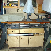
dusty wrote:I don't know what you or others are considering to be "too high" but doing what I said puts the wheels just off the ground (about 1/16") when the legs are grounded. In the intermediate lift position, the legs are off the ground and the Mark V can be moved. In the upper position, the legs are off the ground about 1/2" (I did not measure it).
Well then I would say you got the right info and my trust in SS is being restored.
Thanks for letting us know.
Ps when I said too high I meant the mounting position was too high on the legss However you have proved that wrong.
I have completed the 3" Caster Upgrade and I believe that it works well. If there were problems with the installation instructions or with the templates provided by Shopsmith, those have in my opinion been resolved.
I cannot tell you what is different because I don't have the old instructions or the old templates. I would post images of the instructions and templates but I am going to treat them as though they are copyrighted.
Hopefully, Admin will add them to the online documentation.
I can, however, tell you how I installed the casters because I did it my own way. I used the template to make a drill guide. I bolted the drill guide to the leg I wanted to drill and "did it". Four times and I was done drilling. I drilled 1/4" rather than the 9/32" holes called for in the procedure. I did this to take the slop out of the drill guide and ultimately the mounting bolts. There is still some slop because the holes in the caster assemblies are quit a bit larger than 1/4".
With the Shopsmith upright and grounded on all four legs, I bolted the caster assemblies with casters installed to the legs of the Shopsmith. The only hard part was getting up and down four times.
[ATTACH]17450[/ATTACH]
[ATTACH]17451[/ATTACH]
[ATTACH]17452[/ATTACH]
This is my interpretation of the hole locations as I have drilled them in my Mark V.
Attachments
New Caster Template and Application 010 (Custom).JPG (59.45 KiB) Viewed 4800 times
All Four Holes in a Line (Custom).JPG (68.05 KiB) Viewed 4805 times
Wheel Just Off the Ground (Custom).JPG (60.24 KiB) Viewed 4805 times
New Caster Drilling Dimensions2 (Custom) (2).jpg (19.31 KiB) Viewed 4701 times
"Making Sawdust Safely" Dusty
Sent from my Dell XPS using Firefox.
JPG40504 wrote:That would be my conclusion as well.
AIUI the 'older' template put the new hole centers about 1 3/4"[???] above the original holes. Gotta be careful here. Remember, the holes are located on a line that is not vertical. Distance down to the ground and distance between holes is measured in two different planes and yields slightly different results.
Earlier discussion and descriptions of resultant floor clearance(as well as Ed's thread) indicates that they need to be lower at about 1 9/16".
We are eagerly awaiting your divulging the result of using the newer template(how much the holes are moved up).
I do not understand what the different hole spacing for the original casters was about.
I posted an attachment with measurements.
"Making Sawdust Safely" Dusty
Sent from my Dell XPS using Firefox.
I went out and measured the location of Dusty's new hole where he has 5-1/8, and that is the same as what I have! But before we celebrate too much....
Where he has 3-5/8 mine measures 3-3/4 or an eight inch different. The effect of this is that mine needed to be moved less the his to get to the same new hole location.
The conclusion I'm leaning towards is this:
The bad news is there is only one template, that being for the new legs, and then vintage I have (late 70's) needs a new template.
The good news we may have solved this. The spacing as shown on Dusty sketch has a spacing of 1-11/16 from old hole to new hole. If we adjust that by the 1/8" we get 1-9/16".
So with the information we have thus far it appears we at the forum have again shown that a group of people working together in a cooperative effort can solve problems like this and earned our worth. (If this new makes it back to shopsmith and they fix things it will be even better.)
I want to thank Dusty for his efforts on this thread.
I was very pleasantly surprise to find that shopsmith shipped the colored manual with great pictures unlike the photocopy I got with "mud" pictures. Good on them!
The template would now appear to be correct for the more recent legs, I think the template I have was an attempt to fix things but they went the wrong way, actually giving less height rather then more. Having Dusty doing his mounting show promise of this.
I would be interested in seeing the wheels in both raised positions with a piece of 1/4" and 1/2" plywood slid under the legs. To me this is still a very important proof of design item.
I also like the way Dusty went about the drilling and mounting. I went a different route which worked OK too. I can not see me flipping my machine for this or any other upgrade. For one thing I'm not as strong as I would need to be to do this and might require two helpers of which could be a problem. All the old friends are just that, old. Kids are so busy trying to get them here at the same time would be almost impossible...
reible wrote:I want to thank Dusty for his efforts on this thread.
I was very pleasantly surprise to find that shopsmith shipped the colored manual with great pictures unlike the photocopy I got with "mud" pictures. Good on them!
The template would now appear to be correct for the more recent legs, I think the template I have was an attempt to fix things but they went the wrong way, actually giving less height rather then more. Having Dusty doing his mounting show promise of this.
I would be interested in seeing the wheels in both raised positions with a piece of 1/4" and 1/2" plywood slid under the legs. To me this is still a very important proof of design item.
I also like the way Dusty went about the drilling and mounting. I went a different route which worked OK too. I can not see me flipping my machine for this or any other upgrade. For one thing I'm not as strong as I would need to be to do this and might require two helpers of which could be a problem. All the old friends are just that, old. Kids are so busy trying to get them here at the same time would be almost impossible...
Ed
I was going to lay it down. Actually I started to do that but got it part way down and realized that I was not going to be able to complete that maneauver gracefully. Back to upright.
I then thought about putting it on a pair of saw horses and rolling it. I have done that before and it works real well BUT I decided I did not want to work that high to drill those holes. My back, shoulders and arms would likely have turned this into a two day job.
So, to the floor it was. Worked fine except when I had to stand up and relocate.
I will do that 1/4" and 1/2" plywood check tomorrow, Ed.
"Making Sawdust Safely" Dusty
Sent from my Dell XPS using Firefox.
reible wrote:I want to thank Dusty for his efforts on this thread.
I was very pleasantly surprise to find that shopsmith shipped the colored manual with great pictures unlike the photocopy I got with "mud" pictures. Good on them!
The template would now appear to be correct for the more recent legs, I think the template I have was an attempt to fix things but they went the wrong way, actually giving less height rather then more. Having Dusty doing his mounting show promise of this.
I would be interested in seeing the wheels in both raised positions with a piece of 1/4" and 1/2" plywood slid under the legs. To me this is still a very important proof of design item.
I also like the way Dusty went about the drilling and mounting. I went a different route which worked OK too. I can not see me flipping my machine for this or any other upgrade. For one thing I'm not as strong as I would need to be to do this and might require two helpers of which could be a problem. All the old friends are just that, old. Kids are so busy trying to get them here at the same time would be almost impossible...
Ed
FWIW Ed, I received the same template as you did and it did not line up with the holes on my 50th Anniversary 520. So I don't know that they have changed the hole pattern in the legs over the last 50+ years. I moved my holes up 1-5/8" along the centerline of the existing holes.
I was going to wait until tomorrow but as I sat here, watching news that I did not want to hear, I suddenly found myself in the shop.
The results of the test are somewhat disappointing if I used 1/4" and 1/2" as the clearance requirements for mid position and upper position respectively.
The inconsistencies that I witness may be the result of small undulations in my concrete floor (which was in the early years a simple car port).
All four legs bottom out in the down position. The Mark V seems stable. After all of this, I will have to make some alignment checks but I expect them to be fine.
In the next raised position, I can insert 1/8" shims under all four legs. They are loose. I can insert an additional 1/8" shim (1/4") under only one leg. The other three vary but not enough for the second shim.
In the upper position, I can insert a 1/2" shim under one leg and another under a 2nd leg but it is much tighter. The other two will accept a 1/4" plus a 1/8" shim. One is snug and the other is almost snug.
Bottom Line: My installation and my caster assemblies do not pass the 1/4" and 1/2" test that Ed has suggested. I believe the margin is close enough that I could get there by enlarging the mounting holes but as long as I have stability in the down position (all four legs grounded) and sufficient clearance to move it around in the mid position, I am not going to do that.
In the upper position, I have plenty of clearance for movement on my floor. Some folks may have a terraine that is uneven enough to be a problem - but I really don't think so. I would be surprised.
While we are discussing this, can anyone tell be why there are two up positions.
BTW: I am going to take the caster assemblies off tomorrow and turn they around. I have the petals on the operators side. I also have an Accessory Tool Board there. The tool board makes it difficult to operate the foot pedal.
I am going to move the pedals to the back side.
PS: The clearances on the other Mark V, with original 2" casters, are equally inconsistent. Is it my floor or is it something else. I don't know but for now - it is what it is!
"Making Sawdust Safely" Dusty
Sent from my Dell XPS using Firefox.
The reason for the two positions is to enable you to easily lift the machine. If they only had one position it would be very difficult (impossible?) to turn the level in one shot.
Since the template did not work for me I am going to get 12 washers tomorrow and solve the problem the easy way it should also help with not hitting the color with the lever since I did not move the lever as recommended. I also think I will put the lever in the back because I also have the auxiliary shelf that makes it hard to reach the lever.
Paul Cohen
Beaverton, OR
A 1982 500 Shopsmith brand upgraded to a Mark 7 PowerPro, Jointer, Bandsaw (with Kreg fence), Strip Sander, Ring Master and lots of accessories all purchased new
12" Sliding Compound Mitre Saw, 1200 CFM DC
I got the washers and found something very interesting and something I can't explain. I used the same templates for both legs (I checked them). On the right side I need 1 washer to get the desired 1/4 and 1/2 rise and the washers are really unnecessary. On the left side I need 5 washer to get the desired elevations, without the washers even in the second position the legs barely clear the floor, you can't get 1 washers under them.
What explains the different in the legs? Why did I not have this issue with the old casters.
I have not yet installed the washers because I need help lifting the machine. I don't even know if I can get 5 washers in or should I redrill the holes.
Paul Cohen
Beaverton, OR
A 1982 500 Shopsmith brand upgraded to a Mark 7 PowerPro, Jointer, Bandsaw (with Kreg fence), Strip Sander, Ring Master and lots of accessories all purchased new
12" Sliding Compound Mitre Saw, 1200 CFM DC