With the masonry mortises cut and the wall framing exposed, I could finalize the corbel length, and it was time to start cutting the beam. But the only tool in my arsenal that could cut clear through that big beam was my chainsaw, and I needed tighter tolerances than I could manage with it. At the time, I didn’t have the hand tools, or the hand-tool know-how, to clean up rough cuts on such a big piece.
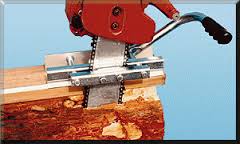
So after some more web research, I decided to buy a “Mini Mill II” from Granberg International. This is basically a bracket that clamps to the bar of your chainsaw, and guides the chainsaw down a section of inverted V-track that you mount to a straight guide board. The guide board is normally screwed to a rough log. In my case, I just clamped it to the resawn beam.
The Mini Mill worked very well indeed. It looks unwieldy (see the stock photo below), but is surprisingly well-balanced and accurate in use. I made an initial test cut to calibrate kerf width and offset, and to check squareness. Once calibrated, I was amazed to find that I could make nice square cuts to a layout line with an accuracy of about +/- 1/16”.
- mini mill.jpg (7.17 KiB) Viewed 5290 times
The component layout on the beam was simplicity itself. The center of the beam would be the mantel. Just outboard of that would be the two corbels. The most badly checked few inches at each end of the beam would be waste material.
The first cut was to remove the waste pieces, and that was a darned good thing. Cut free, those sections literally fell apart. So the checking extended well into the corbel sections. I found that the tops and bottoms of each corbel piece were sound, but that there were deep fissures dividing the top and bottom along the pith. After an extended “Aw crap!” moment, followed by some more head-scratching, I decided to reinforce the corbels before cutting them free of the beam. I installed four 3/8”x6” lag screws vertically in each corbel. The screw heads were recessed into counterbores on the top surface, where they would be hidden by the mantel beam. This solidly tied the top and bottom sections together. Only then did I saw the corbels off of the beam.
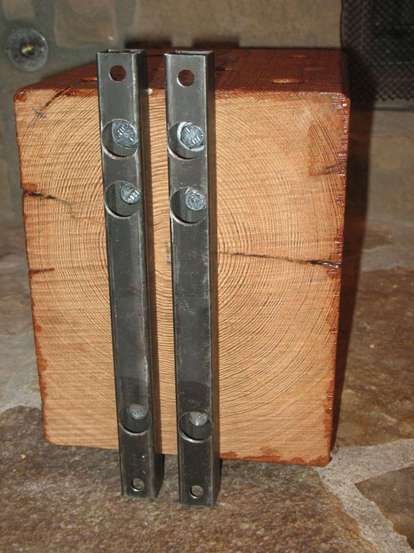
In the photo below, you can see the deep horizontal fissures threatening to split the corbel in two – but now bridged by the vertical lag screws. You’ll also notice that the brackets are mounted slightly off-center on the corbel. That was done intentionally, to match the position of the doubled 2x4 studs in the masonry mortises.
The rear of the corbel shows the surprisingly good surface finish produced by the Mini-Mill mounted chainsaw. Although the tooth marks are straight instead of circular, the surface roughness was very similar to what that antique sawmill produced on the sides of the beam. On the exposed front surfaces, I again just smoothed the surface roughness a bit with hand sanding, and otherwise left the saw marks in for character.
- Corbel brackets.jpg (538.38 KiB) Viewed 5290 times
To mount the brackets to the corbel, I used lag screws in the middle and lower positions. But I didn’t trust them for the top positions, as they would be in end-grain, and the weight of the beam would be working to pull them out. So instead I bored clearance holes for 3/8” machine screws, and made intersecting bores from the top of the corbels for the washers and nuts. This is where my new-to-me Shopsmith came in mighty handy. The machine-screw bores were about 5” deep, and had to accurately intersect the cross bores. With my 520 in horizontal boring mode, it was a piece of cake. I clamped the corbels to a miter-gage fence and backed them up with the rip fence. The resulting bore centerlines intersected to within about 1/16”, no problem.
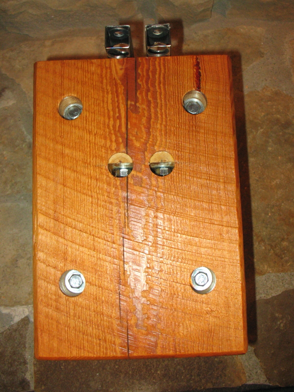
The photo below shows the heads of the vertical reinforcing screws, and also the nuts on the machine screws. To provide a flat surface for the nuts to seat, I turned a dowel to the bore diameter, split it in two, and glued it in place. In hindsight, I should have simply cut a square face into the bore with a chisel – that half-bore was a darned tight fit for an end wrench. But I don’t think I even owned a decent chisel at the time, and I quite obviously didn’t know what they were useful for.
- Steel.jpg (553.2 KiB) Viewed 5290 times
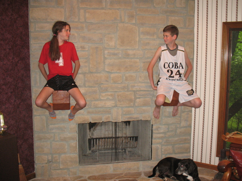
With the brackets attached to the corbels, mounting them to the wall was simplicity itself. A 3/8” lag screw in the top and bottom of each bracket gave a total of 8 beefy screws into the wall framing, which in turn was reinforced by all that masonry. To test it, I used my own 200lb carcass as a live load on each corbel, and the hardware handled it with ease. So for fun, I grabbed a nearby daughter and perched her on one of the corbels. This led to much silliness and goofball posing by all three kids.
- Twins.JPG (508.32 KiB) Viewed 5290 times
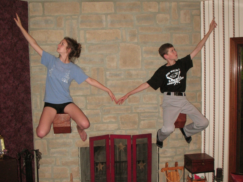
- Ballet.JPG (479.77 KiB) Viewed 5290 times
Then I mixed up some ready-mix mortar and jointed completely around the periphery of each corbel. After the mortar dried, the corbels were locked in on all sides, and felt as solid as the beam itself.
To be continued ...
 Seriously though, all that checking around the pith did indeed present a structural "problem-solving opportunity" on the corbels.
  More on that later.
 Your sketch was right on!!
