Page 2 of 3
Re: Mark VII speed control
Posted: Thu Oct 15, 2015 9:59 pm
by richardrouse
The speed control looks to be viable, however I need to refine a few characteristics of the part. It will, however, change speeds up and down the whole range
Re: Mark VII speed control
Posted: Thu Oct 15, 2015 10:20 pm
by JPG
richardrouse wrote:The speed control looks to be viable, however I need to refine a few characteristics of the part. It will, however, change speeds up and down the whole range
?????
Shaft pin hole? Profile???
Re: Mark VII speed control
Posted: Thu Oct 15, 2015 10:54 pm
by richardrouse
Angular location of the pin hole. I think I'm off by a few degrees.. The low speed on my dial reads as 1200 rpms and high speed is off the chart. That's 1200 on the dial, not 1200 actual. I didn't put the tach on it to read the actual speed.
Other than that, the part might be too wide, but I'm not going to make it any skinnier than the original, part of my problem is worn belts.
Re: Mark VII speed control
Posted: Thu Oct 15, 2015 11:13 pm
by JPG
Worn motor belt will alter the speed achieved. Narrow belt results in faster speed. (narrow belt rides further out on the motor pulley, and further in on the idler pulley).
Back to the motor! My memory is shot!!!! My Mark VII motor is the same as yours! The brass weights rotate and that pulls the actuator 'springs' and 'black part' away from the switch 'rub pads'. The black part(brown in my motor) slides on the shaft.
There are spacers that mount the actual start switch. They affect the amount of contact pressure/wipe. There are TWO contacts that should be wired in parallel.
I will post links to 'my' assembly of the motor.
Re: Mark VII speed control
Posted: Thu Oct 15, 2015 11:27 pm
by JPG
The link shows all(but one part) of the armature hardware.
The post following that one shows the start switch mounting. Note the use of THREE spacers to mount the switch.
Sorry I did not remember all this earlier!!!
 http://www.shopsmith.com/ss_forum/viewtopic.php?t=11986
I will be editing those posts to place the pix back into the text as done originally.
Re: Mark VII speed control
Posted: Fri Oct 16, 2015 10:18 am
by richardrouse
No worries!!
I do appreciate all of the help thus far. The motor works one second and it doesn't the next. I'm missing parts for the starter switch / rub plate which makes me feel less crazy.
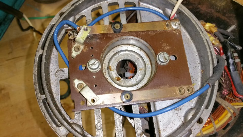
- 2015-10-16 10.14.50.jpg (147.66 KiB) Viewed 2389 times
Starter switch missing paralell contacts.
I soldered it like so because it was the way it came out of the motor.
It doesn't even have the solder pad for the second contact.
I only had that spacer thing in the front end cap.
Re: Mark VII speed control
Posted: Mon Oct 19, 2015 11:47 am
by richardrouse
The control cam is ready. JPG, I have fixed the dimensional issues on the holes that was discussed.
The pin hole measures precise, the main bore is slightly undersized, this will have to be sanded or filed out by the user to get a good fit on their particular shaft... now that just sounds dirty

There is a utube video below if you want to see it in motion / action.
https://youtu.be/b07svtnY__Y
Now... on to the rack.
Re: Mark VII speed control
Posted: Fri Nov 06, 2015 9:47 pm
by JPG
A tale of three cams.
[A] My MVII came with a third party aluminum cam.
I had already obtained a CNC produced copy.
[C] I recently received one as described above.
A was different from B
C is very close to B
A is red B is black C is White
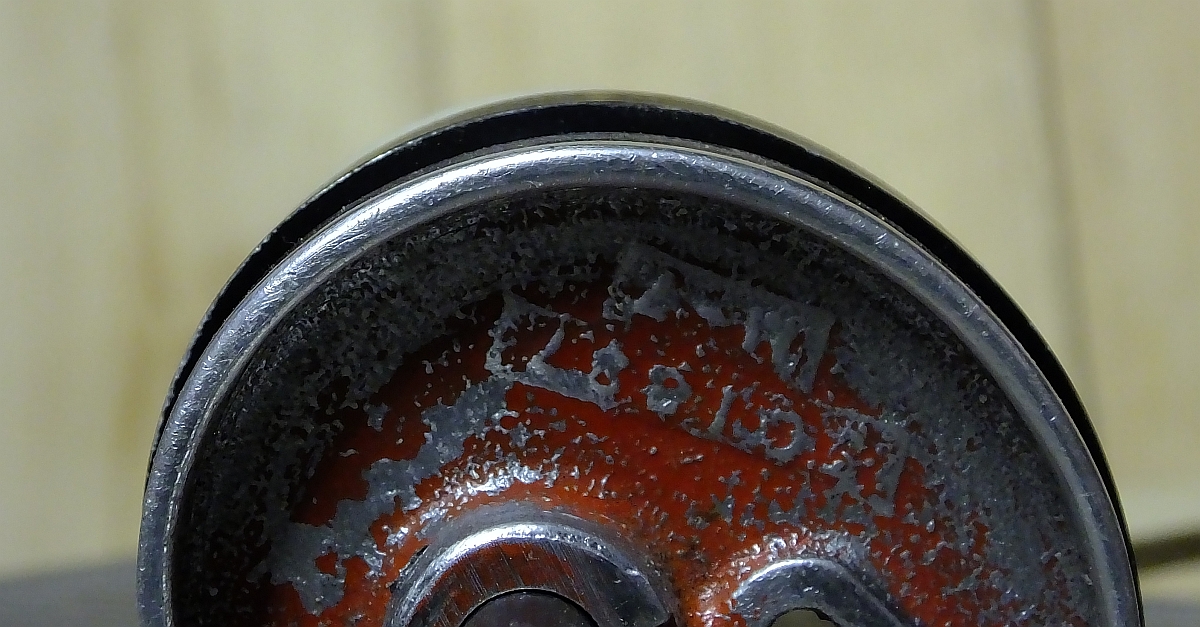
- CAM AL-AL.jpg (539.06 KiB) Viewed 2333 times
The black cam
is silver(aluminum) in the second pix since I filed down that edge.

- CAM PL - AL.jpg (320.47 KiB) Viewed 2333 times
FYI
Re: Mark VII speed control
Posted: Sat Nov 07, 2015 8:08 am
by richardrouse
I hadn't seen just how flattened out that part of the cam had become. I wonder if that is due to distortion in the nylon cam i based it on.
I'll have to adjust the model.
Can you, by chance, take a photo of the silver cam's profile head on with a scale in the background? so I can compare the profile I used to create the model and the CNC cam.
Re: Mark VII speed control
Posted: Sat Nov 07, 2015 8:28 am
by BuckeyeDennis
I've done a bit of cam design for converting old cam machine tools to CNC, and I'd bet that cam is supposed to be "linear" -- i.e. a straight line in polar coordinates. Radius = k * Angle. That should be easy to check if you already have a model.
It's also possible to tweak the cam profile to compensate for the slightly nonlinear cam-follower kinematics, but I doubt they would have bothered.