Page 2 of 5
Re: Is my Mark VII motor/switch wiring correct?
Posted: Sat Apr 08, 2017 11:10 pm
by JPG
Asking for the color of the wires emanating from that little hole in the motor case would to me seem simple enough.
It is a beginning to determine whether you have a GE Mark VII motor that heretofore has never been mentioned.
'We' are aware of a Mark VII GE motor without an external relay and that its colors differ from other 'makes' of Mark VII motors.
IF yours is indeed a GE Mark VII motor with external relay, 'we' would be very interested in helping you decipher the wiring. However that cannot begin until 'we' know the colors of ALL wires that come out of that little hole.
No guarantee of success, but 'we' be willing to try.
Later measuring resistance to determine internal interconnections may be required.
'We' will likely need to know the color of the wire(s) connected to the start capacitor.
P.S. Since the mounting of the motor for Mark 5 and Mark VII is different it is unlikely(not impossible) that you have a mark 5 motor.
Re: Is my Mark VII motor/switch wiring correct?
Posted: Sat Apr 08, 2017 11:15 pm
by n240sxle91
Ah ha! I see now where you are going with this. I will get all of the wire colors, and where they go posted tomorrow. I'm guessing the motor was replaced with a single direction motor, but it would be exciting to have a rare mark vii motor! Thanks again for the help!
I'll be back tomorrow!
Re: Is my Mark VII motor/switch wiring correct?
Posted: Sun Apr 09, 2017 1:22 pm
by n240sxle91
Here is what I found.
Motor's hole has 6 wires
-Black
-White
-Blue
-Yellow
-Brown
-Red
Relay has 3 pins
-Yellow / Maroon (share a pin)
-Orange
-Brown
Motor Start Capacitor
-Brown (goes to motor hole)
-Brown (goes to relay)
Motor Green Screw - Green (Power cord)
Switch
L2 White
L1 Blue
T5 Orange
T9 empty
Bottom L2 Black (power cord)
Bottom L1 Cream (power cord)
5 Blank
2 Red
5 Blank
Notes: The black wire from motor hole and maroon wire from the relay have a jumper wire connecting them. This seems to have been done by the previous owner).
Re: Is my Mark VII motor/switch wiring correct?
Posted: Sun Apr 09, 2017 1:46 pm
by JPG
You have done an excellent job of documenting the status quo.
I think it can be deciphered as to what is 'correct'(or at least equivalent).
I think some power on verification of whether the motor will act correctly by manually connecting the wires is a good initial step. I believe since the motor wire colors are the same as the GE motor with internal start switch that that can be done both predictably and safely. It will depend upon correct following of connections on your part and clear instructions from here. I have faith in your part considering your last post.!
I agree a previous owner disabled the reverse function. Question is, WHY? I am suspicious it was because the switch stopped working properly. That is why I consider not using the switch initially so as to preclude any confusion it might create.
If the switch IS funky it can POSSIBLY be 'fixed', but that may be prone to be temporary(the contacts lose their spring when over heated).
Again you got an ohmmeter???
Re: Is my Mark VII motor/switch wiring correct?
Posted: Sun Apr 09, 2017 1:59 pm
by n240sxle91
Thanks again for your help!
I do have an ohmmeter. I also have two switches. I bought one on Ebay when I thought mine was broken (it still might be). So, I have two switches I can test with.
I agree some quick testing by manually connecting the wires is a good place to start. I'm pretty sure I can do that with your help and directions.
Looking forward to getting started!
Re: Is my Mark VII motor/switch wiring correct?
Posted: Sun Apr 09, 2017 2:50 pm
by everettdavis
Your picture shows a GE with an external motor start relay.
See if this helps....
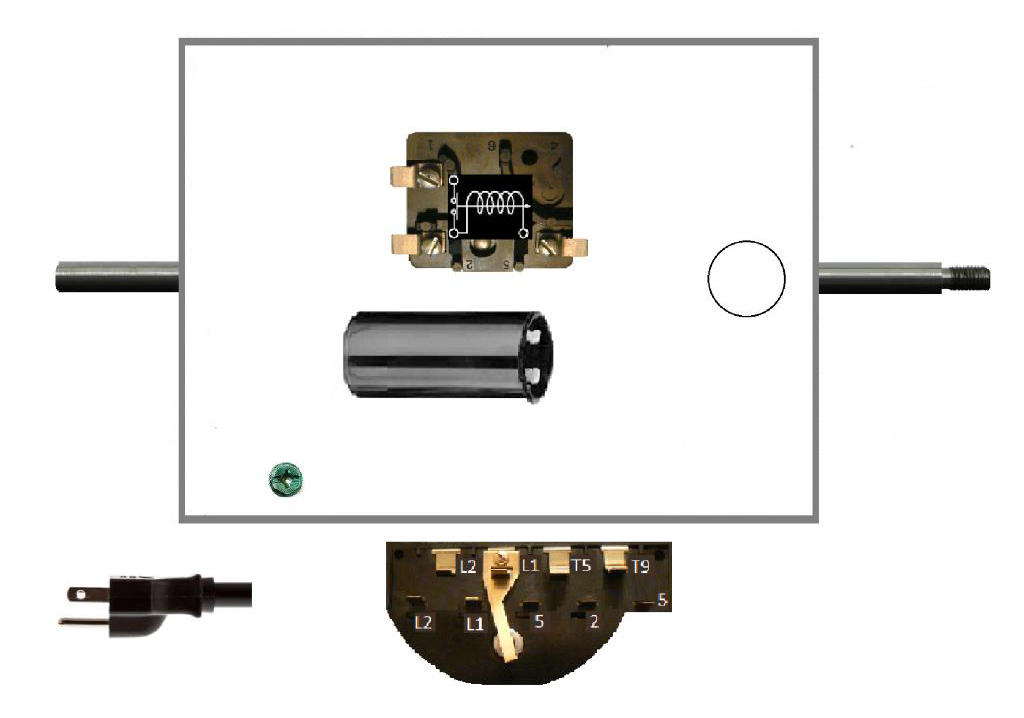
- Draw Your Own GE Mark VII motor with External Relay.png (222.32 KiB) Viewed 5190 times
https://drive.google.com/drive/folders/ ... WRUSUttbk0
Has the others that I did when I restored the MARK VII Owner's Manual which you will find there too.
There are drawings for the other 3 motor types there, but neither JPG or I had one of the GE with External Relay motors to match up wires from.
If yours is that one, I will be happy to make another motor type drawing, just draw what you have on the attached draw your own illustration.
helpful to do that when you take apart what you had regardless if it is right or wrong, we can usually spot what's wrong.
I think you will find the other AO Smith motor with external start relay a bit of help to envision what you have.
Everett
Re: Is my Mark VII motor/switch wiring correct?
Posted: Sun Apr 09, 2017 4:34 pm
by JPG
For starters, add relay terminal numbers to Everett's blank.
1 label the upper left terminal(1) - I believe you currently have a BRowN wire from the capacitor connected there on your relay.
2 label the lower left terminal(2) - I believe you currently have an ORaNge wire connected there.
3 label the lower right terminal(5) - I believe you have the YELlow and purple wire there. I prefer to call it VIOlet.
If the wires are not connected as I described above, stop and tell me so.
You should have the motor connected to the switch as follows(I assume that portion of the switch is still working).
L1 BLUe
L2 WHIte
The Line Cord is connected to L1 and L2 And a grounding screw.(FWIW your linecord WHI/BLK wires are 'reversed' - it will work either way).
That leaves the RED,BLacK motor wires and the ORaNge and VIOlet wires from the relay 'dangling'.
Again if yours are not connected EXACTLY as I just described, stop and let me know.
Now for the 'moment of truth' !
Temporarily connect the ORN wire to the RED motor wire
Temporarily connect the VIO wire to the BLK motor wire
There should NOT be any unconnected wires.
plug in the line cord and push the switch on(be prepared to immediately pull the plug).
It should run.
Unplug it and swap the RED/BLK wires RED to VIO and BLK to ORN
Plug it in and turn on as before
It should run reversed.
I have to turn away from thus but will return this evening - do let me know our status if you have proceeded.
Re: Is my Mark VII motor/switch wiring correct?
Posted: Sun Apr 09, 2017 5:34 pm
by n240sxle91
Success!! It worked both forward and reverse!
I'll try both switches and report back.
Thanks so much!
Re: Is my Mark VII motor/switch wiring correct?
Posted: Sun Apr 09, 2017 6:00 pm
by JPG
n240sxle91 wrote:Success!! It worked both forward and reverse!
I'll try both switches and report back.
Thanks so much!
Slow down grasshopper!!
Wire the RED/BLK/ORN and VIO wires to the switch as follows.
But before doing that let's determine if the reversing part of the switch works properly.
The switch has three positions forward, off, and reverse.
I assume you know which button to push for each position.
So get out yer ohmmeter and check the following:
Switch
forward. T5 to 5(middle one) T9 to 2 <<<< s/b
reverse
Switch
reverse. T5 to 2 T9 to 5(outer one) <<<< s/b
forward
IFF ok connect motor wires as follows:
RED to T5
BLK to T9
other wires:
ORN TO 2
VIO TO both 5(JUMPER THE TWO '5')
That should be it.
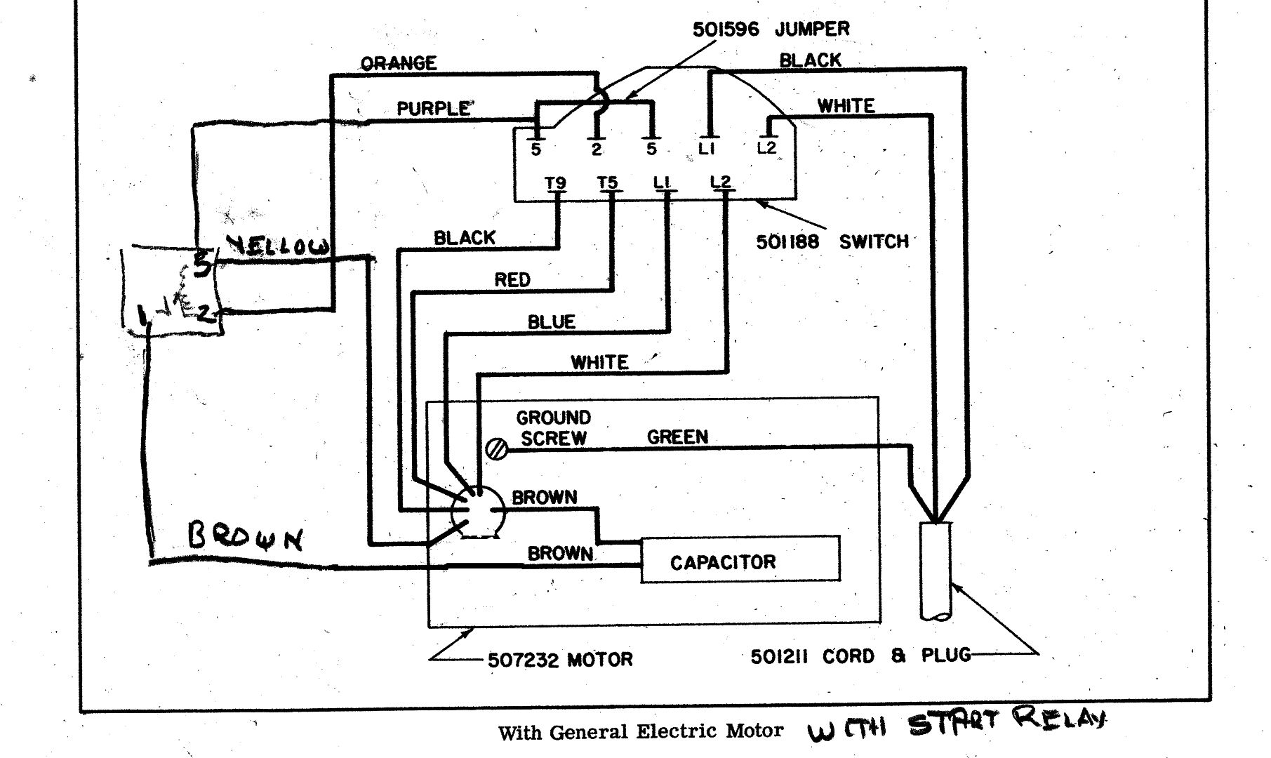
- MVII GE MOTOR WITH RELAY.jpg (196.12 KiB) Viewed 5152 times
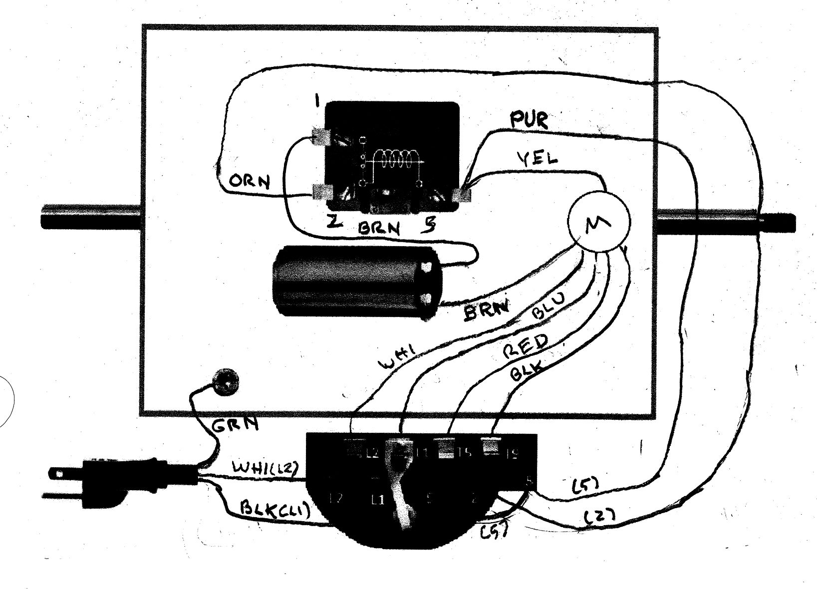
- MVII GE MOTOR WITH RELAY B.jpg (208.87 KiB) Viewed 5152 times
Re: Is my Mark VII motor/switch wiring correct?
Posted: Sun Apr 09, 2017 6:05 pm
by n240sxle91
Sounds good. I'll wait for further instruction.
