Page 2 of 4

Re: 10ER speed changer

Posted: Fri Apr 14, 2017 12:21 pm
by rpd
Ok, got the floating pulley assembly apart except for one of the bushings.

I used solvent, a heat gun, and a bit of friendly persuasion ;) (bearing puller.).
SCdisassembly2.JPG
SCdisassembly2.JPG (267.13 KiB) Viewed 11191 times
SCdisassembly3.JPG
SCdisassembly3.JPG (271.17 KiB) Viewed 11191 times
SCdisassembly4.JPG
SCdisassembly4.JPG (265.23 KiB) Viewed 11191 times
I think the biggest problem is the PO did not read the part about using NON GUMMING oil. :(
There is also a small amount of rust inside the floating sheave an on the shaft. I think it should polish off without much trouble. :)

Re: 10ER speed changer

Posted: Sat Apr 15, 2017 1:36 am
by rpd
Got the pulley shaft cleaned and polished, :)
Mounted a short piece of wood in the chuck and turned a cone on the end, live center in tailstock and turned it between centers. ;) Shopsmith heal thyself. :cool:
SCpolishing1.JPG
SCpolishing1.JPG (337.89 KiB) Viewed 11166 times
I used metal polish, (Autosol), on a shop-towel, and then finished with honing compound on a leather strop.
SCpolishing2.JPG
SCpolishing2.JPG (361.27 KiB) Viewed 11166 times
SCpolishing3.JPG
SCpolishing3.JPG (359.19 KiB) Viewed 11166 times
There are still a few faint marks but I don't want to remove too much metal.
Next, turn a mandrel to hone the inside of the pulleys.

Re: 10ER speed changer

Posted: Sat Apr 15, 2017 12:19 pm
by beeg
I hope that the shop towel was a paper one knot a cloth one :eek: .

Re: 10ER speed changer

Posted: Sat Apr 15, 2017 1:34 pm
by rpd
beeg wrote:I hope that the shop towel was a paper one knot a cloth one :eek: .
No fear, it was the blue paper kind. :)

Re: 10ER speed changer

Posted: Sat Apr 15, 2017 2:11 pm
by ERLover
beeg wrote:I hope that the shop towel was a paper one knot a cloth one :eek: .
Why?

Re: 10ER speed changer

Posted: Sat Apr 15, 2017 2:50 pm
by rpd
Cleaned out the inside of the floating sheave by hand with Autosol polish on a shop-towel, now it slides freely on the shaft. I washed the sheaves with dish detergent and water and scrubbed them lightly with Scotchbrite.
SCpolishing4.JPG
SCpolishing4.JPG (288.2 KiB) Viewed 11135 times
And reassembled, heating the shaft with a heat gun aided in reinstalling the bushing.
SCpolishing5.JPG
SCpolishing5.JPG (280.33 KiB) Viewed 11135 times
Next, the screw assembly. Washed with tooth brush and Scotchbrite, and polished with Autosol.
SCpolishing6.JPG
SCpolishing6.JPG (310.71 KiB) Viewed 11135 times
I wasn't trying for a mirror finish, just clean and functioning.
ERLover wrote:
beeg wrote:I hope that the shop towel was a paper one knot a cloth one :eek: .
Why?
When using a lathe there is a danger that a cloth could get caught and cause injury, a paper towel would just tear.

As Cap'n Eddie says "The only rags that come near my lathe are the ones I am wearing."

Re: 10ER speed changer

Posted: Sat Apr 15, 2017 3:23 pm
by beeg
ERLover wrote:
beeg wrote:I hope that the shop towel was a paper one knot a cloth one :eek: .
Why?
Because a paper towel will tear if it gets caught. A cloth towel will wrap round the object possibly pulling your hand/fingers with it. :eek: :eek:

Re: 10ER speed changer

Posted: Sun May 07, 2017 12:48 pm
by rpd
Got the broken plate cleaned up and made some repair plates from some aluminum angle I had on hand.

Here I have glued the broken part together with thick CA glue, the repair plates are in the foreground.
SCglued1.JPG
SCglued1.JPG (326.22 KiB) Viewed 11050 times
And here the repair plates are put in place with JB Weld epoxy.
SCglued2.JPG
SCglued2.JPG (276.13 KiB) Viewed 11050 times
While the JB Weld is setting up I have set on the way tubes at the top of my 10ER drill press to ensure everything stays in alignment. :)

Next I will drill the center hole and maybe add some pop-rivets for added strength.

Re: 10ER speed changer

Posted: Mon May 08, 2017 2:08 pm
by everettdavis
rpd wrote:Got the broken plate cleaned up and made some repair plates from some aluminum angle I had on hand.

Here I have glued the broken part together with thick CA glue, the repair plates are in the foreground.

SCglued1.JPG

And here the repair plates are put in place with JB Weld epoxy.

SCglued2.JPG

While the JB Weld is setting up I have set on the way tubes at the top of my 10ER drill press to ensure everything stays in alignment. :)

Next I will drill the center hole and maybe add some pop-rivets for added strength.
I understand that aluminum can be a challenge to weld without the right set-up for it.

Earlier this year I was in the market for a small MIG welder and bought an Eastwood 135A unit based on several friends who have them recommending it. It ran on 110V.

Before I actually unboxed it I called Eastwood and found that there was a Spool Gun option that would allow me to weld aluminum that cost just over $200.

I decided after talking with Eastwood, that rather than keep the 135A unit and buying the spool gun, I would exchange it for the 175A MIG that ran on 220V that in addition to doing all the 135A did, it could weld thicker material, and came with the Spool Gun and Aluminum wire. They were really good working with me, and I got the other unit in quickly.

So if anyone out there reading this Aluminum repair on the speed control sees a MIG in their future, I heartily recommend the Eastwood 175A MIG welder with the spool gun for aluminum.

Today, if I were looking at this option, it is an easy choice. Everything is on sale.

It is less cost to buy the 175A unit at $465.97 which includes the gun and wire, is more capable, has a 50% longer Duty Cycle 30% opposed to 20%, opposed to paying $493 for the 135A ($279) plus the 20172 Spool Gun at ($214).

Considering this thread, and this repair, one also could have repaired it with aluminum weld, then added aluminum plates, bars, etc. to make it stronger and overcome some of the design weaknesses that manifest when it is tightened too much as has been stated.

I would have it mounted on the way tubes to insure alignment was spot on, as I welded it together, likely applying a series of small segment welds to help mitigate tendencies to warp due to heat from welding process itself.

The over-tightening one could mitigate by adding a section of thin-wall sleeve to the bolt to prevent it from bottoming out, allowing the assembly to float with the headstock on the way tubes. One might have to tweak the hole just a bit to clear the sleeve.

I will be interested to hear how the method used for the repair holds up in production. Seems like it would be just fine reading what is being done.

Everett
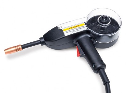
Eastwood Spool Gun.png
Eastwood Spool Gun.png (97.19 KiB) Viewed 11023 times

Re: 10ER speed changer repair

Posted: Thu May 11, 2017 2:27 am
by rpd
Everett, I think welding would have worked great, but I didn't have access to an aluminum welder.

The mended part seems very strong, (and the extruded aluminum shouldn't be as prone to cracking as the cast aluminum is), so I won't be adding screws or rivets at this time.

Drilled the hole with a step bit and finished with a file.
SCfin1.JPG
SCfin1.JPG (261.09 KiB) Viewed 10987 times

and here are the "beauty shots}
SCasembled1.JPG
SCasembled1.JPG (267.68 KiB) Viewed 10987 times
SCasembled2.JPG
SCasembled2.JPG (279.67 KiB) Viewed 10987 times
SCasembled3.JPG
SCasembled3.JPG (266.46 KiB) Viewed 10987 times
When installed the repair plates will be between the headstock and the speed changer, the only part visible will be the top edge.