Page 2 of 3
Re: Time for a new main table?
Posted: Sat Jun 06, 2020 11:08 am
by DLB
Ed - I would like to see that video if you know where it can be found. I agree that the trunnions are a significant factor in this, lesson learned the hard way. But I can't envision how this works. I recall a Nick video in which he added shims (the less expensive kind) between trunnion and table to align the table to be perpendicular, front to back, to the spindle. (Standard setup only sets this left/right.) In that video he used different thickness left/right shims, both on the rear trunnion. Did that twist the table out of flat? I don't think it did or would so I'm at a loss trying to figure out how the $20 bill plays into this. But if it works it is a better method than mine, which took a significant investment of time.
My experience - Removing the table from the trunnions changed it a bit, still nowhere near flat. I flattened it considerably on the bench. When I installed it back on the trunnions it warped again. My error, as I still believe but am open to changing, was that I had the table tilt locked while the table was off. The two trunnions were not forming a plane, so bolting the table to them caused it to twist to match. So I went through the whole process again but loosened the table tilt while I bolted the table to the trunnions so they moved to match the table instead of vice versa. This worked fine. As far as I can tell, any shims present at any of the four mounting holes would make no difference.
- David
Re: Time for a new main table?
Posted: Sat Jun 06, 2020 2:19 pm
by DLB
Okay, here is the reconstruction of the method I used. On mine I reduced the magnitude of the low from something over .060 to something under .003. These pictures are with the table mounted, when I did it I removed the table and did this on the bench. And yes, I know my table is mounted backwards in these photos, left just means as normally mounted, the side closest to the headstock. The left side of the table, starting from the insert, is considerable less robust than the right side. The strongest part seems to be the T-Slot, so I focused on straightening the T-Slot and let everything else follow on its own:
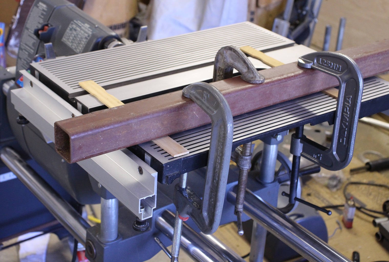
- Table Flattening Setup
- IMG_8555.jpg (507.87 KiB) Viewed 8402 times
I used a scrap of heavy walled (~.120) 2" square steel tubing. It is directly over the T-slot and the bottoms of the clamps are on the T-slot part of the casting. This tube will flex under the load but not as much as the table. Stiffer would be better, but this was adequate. I used steel shims but they can mar the surface, so if I did it again I would use something else. Paint stirring sticks are illustrative only. Thin shims help to keep you from bending the table too much at one time.
Measure your table flaw left to right as well as front to back. Position shims and clamps so that your force is applied where it is needed. On mine, measuring left to right, the table was flat for about the front three inches, so I put my front shim where the defect started. I think I used five C-Clamps when I did this, three is illustrative.
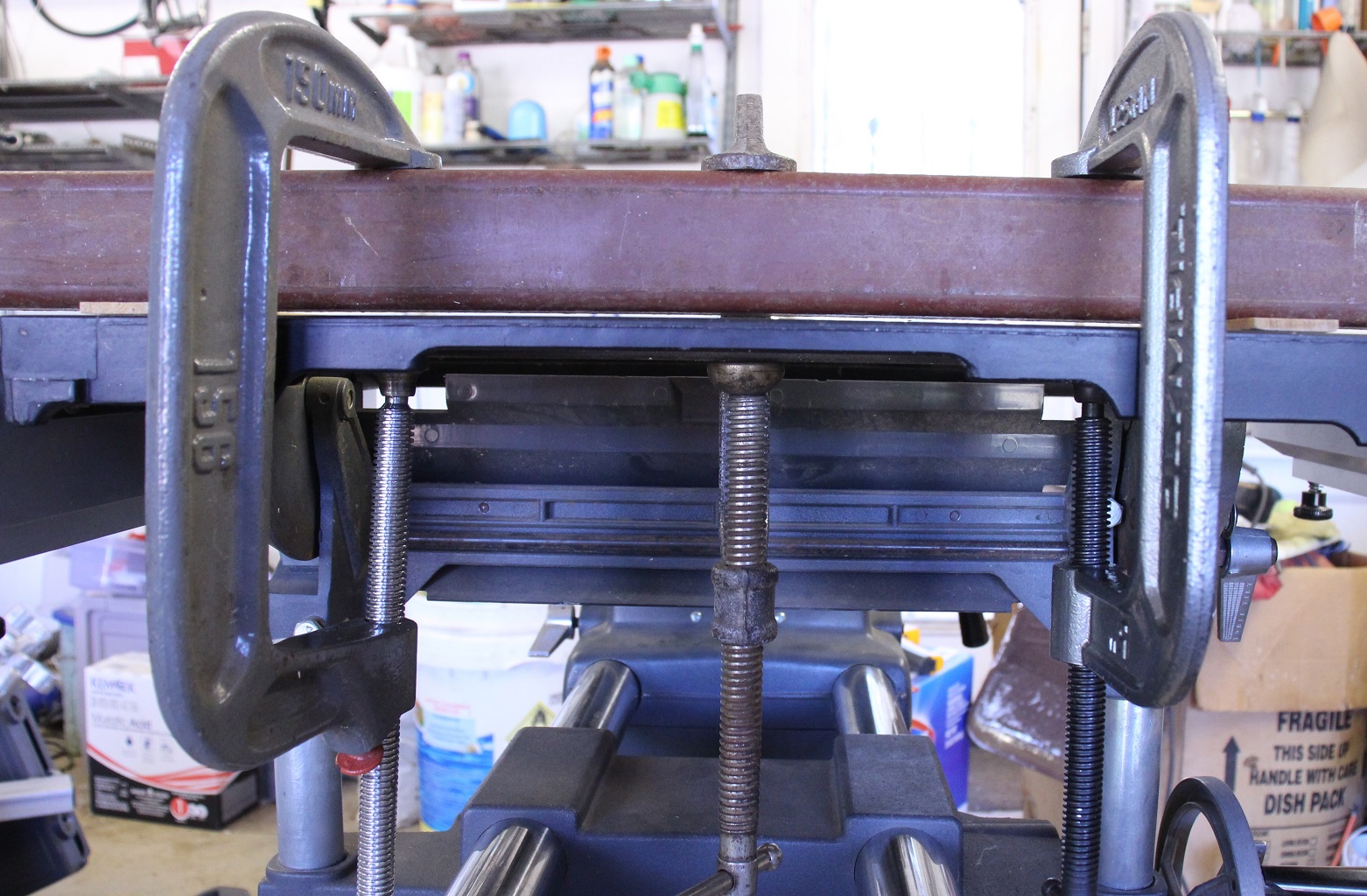
- Gap with clamps
- IMG_8556.jpg (539.5 KiB) Viewed 8402 times
When you start tightening the clamps the table will flatten and then bow up slightly into this gap. Tighten the clamps a little at a time and keep re-tightening all clamps to distribute the pressure. I let mine sit for a while under clamping pressure. I did this over several iterations, relieving the pressure and measuring in between. Sometimes there was no improvement, indicating not enough pressure. My first attempt was without the shims, the table flattened under clamping pressure then went right back where it was when I removed the clamps. For the most part it is a learning process, you'll get a feel for the relationship between pressure applied and result achieved. You don't want to go too far.
This is a brute force method. If we find that there is more elegant solution (the Nick $20 solution) I'd use that instead. My going in position was 'this table is scrap, I can't make it worse.' When you install the table loosen the tilt lock a bit so you pull the trunnions to the table rather than vice versa. And since you have messed up your alignment this would be a good time to think about shimming the front or back trunnion/table junction so the table is perpendicular to the spindle in that direction. This method worked for me and I hope it works for others. It is not without risk of permanent damage.
- David
Re: Time for a new main table?
Posted: Sat Jun 06, 2020 2:50 pm
by dusty
Ed in Tampa wrote:Back in the days of the 510 upgrade ( worst product in Shopsmith history) the first table was warped like yours. I complained to SS and they sent another main table it was better but still warped. I complained again and they sent a third table it was better than first table but worst than the second. I gave up, shoved my Shopsmith into a corner and used it only to sharpen my lawn mower blades for about 20 years.
The SS came out with the 520 and I upgraded and it fixed a whole bunch of things. Then there was a video by Nick that he says use a $20 bill as a shim before you tighten the trunion bolts. Did that and it removed almost all the warp from my table.
I am now convinced, you should setup the machine as described in the setup procedures and no more. Do not look for trouble just use the machine. If things do not turn out “perfect” it is your problem not the machines. If there is a real problem with the machine it probably because you messed up the basic setup trying to reach “setup perfection”.
You better check that $20 bill video clip again. The bill (a feeler gauge) is used to maintain a small gap so that when the table is locked (table tilt) the table does not bind when tilted. It has nothing to do with the table being warped.
Re: Time for a new main table?
Posted: Sat Jun 06, 2020 2:55 pm
by dusty
Now I need some help to understand how this "unflat" table top adversely effects the machine and its ability to perform correctly. The Mark 5/V is not a milling machine.
Re: Time for a new main table?
Posted: Sat Jun 06, 2020 5:29 pm
by DLB
dusty wrote:Now I need some help to understand how this "unflat" table top adversely effects the machine and its ability to perform correctly. The Mark 5/V is not a milling machine.
Mine was a while back, so my memory isn't going to be perfect. I was new to the 520, after using a pre-500 for decades. I was doing alignments per the manual. I was aligning something, perhaps the fence, that put the miter gauge in the left slot, where it was wobbly and wouldn't track correctly. (IIRC, I had just adjusted it in the other slot.) I felt it was unusable as a reference for alignment. Troubleshooting led me to the bow in the table. I researched this forum, maybe my first time, where I found an exhaustive article on the subject, but I eventually realized people were talking about flatness issues an order of magnitude better than my table, and the only solution discussed that would have helped mine was replacement.
I can't say that the originators problem is similar. I first thought it was, but looking at it now I realize the picture is not as clear as I thought. Mine was clearly bowed, with the lowest point right next to the insert and in line with the spindle.
- David
Re: Time for a new main table?
Posted: Sat Jun 06, 2020 5:56 pm
by dusty
I don't doubt for a moment that there are tables out there that are not perfectly flat. I myself have three and they all three fit the basic description of yours. Mine have very shallow dips round about the middle of the table insert area. The only time I experience any adversity that might be caused by that is when drilling holes what needs to be a perfect angle with respect to the surface on small parts. On larger pieces - no problem.
Re: Time for a new main table?
Posted: Sun Jun 07, 2020 6:56 am
by BuckeyeDennis
DLB wrote:Okay, here is the reconstruction of the method I used. On mine I reduced the magnitude of the low from something over .060 to something under .003. These pictures are with the table mounted, when I did it I removed the table and did this on the bench. And yes, I know my table is mounted backwards in these photos, left just means as normally mounted, the side closest to the headstock. The left side of the table, starting from the insert, is considerable less robust than the right side. The strongest part seems to be the T-Slot, so I focused on straightening the T-Slot and let everything else follow on its own:$matches[2]
I used a scrap of heavy walled (~.120) 2" square steel tubing. It is directly over the T-slot and the bottoms of the clamps are on the T-slot part of the casting. This tube will flex under the load but not as much as the table. Stiffer would be better, but this was adequate. I used steel shims but they can mar the surface, so if I did it again I would use something else. Paint stirring sticks are illustrative only. Thin shims help to keep you from bending the table too much at one time.
Measure your table flaw left to right as well as front to back. Position shims and clamps so that your force is applied where it is needed. On mine, measuring left to right, the table was flat for about the front three inches, so I put my front shim where the defect started. I think I used five C-Clamps when I did this, three is illustrative.IMG_8556.jpg
When you start tightening the clamps the table will flatten and then bow up slightly into this gap. Tighten the clamps a little at a time and keep re-tightening all clamps to distribute the pressure. I let mine sit for a while under clamping pressure. I did this over several iterations, relieving the pressure and measuring in between. Sometimes there was no improvement, indicating not enough pressure. My first attempt was without the shims, the table flattened under clamping pressure then went right back where it was when I removed the clamps. For the most part it is a learning process, you'll get a feel for the relationship between pressure applied and result achieved. You don't want to go too far.
This is a brute force method. If we find that there is more elegant solution (the Nick $20 solution) I'd use that instead. My going in position was 'this table is scrap, I can't make it worse.' When you install the table loosen the tilt lock a bit so you pull the trunnions to the table rather than vice versa. And since you have messed up your alignment this would be a good time to think about shimming the front or back trunnion/table junction so the table is perpendicular to the spindle in that direction. This method worked for me and I hope it works for others. It is not without risk of permanent damage.
- David
Thanks David, that makes a lot of sense. I’ve used the same basic technique many times to straighten sheet-metal parts, but it never occurred to me that it could work on a SS table as well.
Like Dusty, the dip in the center of my table is mostly an issue for small parts. I tend to notice it when trying to rip a true 90 degree edge on small workpieces. I could probably improve it with your straightening technique. But then again, making a small-parts sled might be an even better solution for me, because that generally takes table-insert flushness out of the equation as well.
Re: Time for a new main table?
Posted: Sun Jun 07, 2020 9:03 am
by Ed in Tampa
dusty wrote:Ed in Tampa wrote:Back in the days of the 510 upgrade ( worst product in Shopsmith history) the first table was warped like yours. I complained to SS and they sent another main table it was better but still warped. I complained again and they sent a third table it was better than first table but worst than the second. I gave up, shoved my Shopsmith into a corner and used it only to sharpen my lawn mower blades for about 20 years.
The SS came out with the 520 and I upgraded and it fixed a whole bunch of things. Then there was a video by Nick that he says use a $20 bill as a shim before you tighten the trunion bolts. Did that and it removed almost all the warp from my table.
I am now convinced, you should setup the machine as described in the setup procedures and no more. Do not look for trouble just use the machine. If things do not turn out “perfect” it is your problem not the machines. If there is a real problem with the machine it probably because you messed up the basic setup trying to reach “setup perfection”.
You better check that $20 bill video clip again. The bill (a feeler gauge) is used to maintain a small gap so that when the table is locked (table tilt) the table does not bind when tilted. It has nothing to do with the table being warped.
Dusty
I do not know what the original intent of the $20 shim was but I do know it took a major part of the table warp for my machine. I may be wrong but I think Nick did mention that in the video. In any case something he said gave me the idea to try it to remove the warp and it did. In any case I am happy.
Re: Time for a new main table?
Posted: Sun Jun 07, 2020 9:10 am
by Ed in Tampa
DLB wrote:Ed - I would like to see that video if you know where it can be found. I agree that the trunnions are a significant factor in this, lesson learned the hard way. But I can't envision how this works. I recall a Nick video in which he added shims (the less expensive kind) between trunnion and table to align the table to be perpendicular, front to back, to the spindle. (Standard setup only sets this left/right.) In that video he used different thickness left/right shims, both on the rear trunnion. Did that twist the table out of flat? I don't think it did or would so I'm at a loss trying to figure out how the $20 bill plays into this. But if it works it is a better method than mine, which took a significant investment of time.
My experience - Removing the table from the trunnions changed it a bit, still nowhere near flat. I flattened it considerably on the bench. When I installed it back on the trunnions it warped again. My error, as I still believe but am open to changing, was that I had the table tilt locked while the table was off. The two trunnions were not forming a plane, so bolting the table to them caused it to twist to match. So I went through the whole process again but loosened the table tilt while I bolted the table to the trunnions so they moved to match the table instead of vice versa. This worked fine. As far as I can tell, any shims present at any of the four mounting holes would make no difference.
- David
Nick would make videos and post them, most are somewhere in this forum. However I have never been able to find a thing I was looking for in this forum. JPG usually finds the correct forum thread all the time. He is magic. I know the video exists somewhere but I have absolutely no way of finding it sorry!
Re: Time for a new main table?
Posted: Sun Jun 07, 2020 9:54 am
by rpd
Ed in Tampa wrote:DLB wrote:Ed - I would like to see that video if you know where it can be found. I agree that the trunnions are a significant factor in this, lesson learned the hard way. But I can't envision how this works. I recall a Nick video in which he added shims (the less expensive kind) between trunnion and table to align the table to be perpendicular, front to back, to the spindle. (Standard setup only sets this left/right.) In that video he used different thickness left/right shims, both on the rear trunnion. Did that twist the table out of flat? I don't think it did or would so I'm at a loss trying to figure out how the $20 bill plays into this. But if it works it is a better method than mine, which took a significant investment of time.
My experience - Removing the table from the trunnions changed it a bit, still nowhere near flat. I flattened it considerably on the bench. When I installed it back on the trunnions it warped again. My error, as I still believe but am open to changing, was that I had the table tilt locked while the table was off. The two trunnions were not forming a plane, so bolting the table to them caused it to twist to match. So I went through the whole process again but loosened the table tilt while I bolted the table to the trunnions so they moved to match the table instead of vice versa. This worked fine. As far as I can tell, any shims present at any of the four mounting holes would make no difference.
- David
Nick would make videos and post them, most are somewhere in this forum. However I have never been able to find a thing I was looking for in this forum. JPG usually finds the correct forum thread all the time. He is magic. I know the video exists somewhere but I have absolutely no way of finding it sorry!
It is in the first Sawdust Session.
 http://www.shopsmithacademy.com/SS_Arch ... gnment.htm