It occurred to me last night that I could use my CNC as an apparatus for load testing it's own drawer design, and that went quickly and easily today. I'm basically just using the Z axis of the machine as a press, very much like Matthias Wandel did with his apparatus in the video that Ed linked above. But Matthias was pressing on his miniature "drawer" bottoms with a flat pad that was almost as large as the bottom. So he was really testing ultimate strength, not drawer-bottom deflection. My own setup applies all the load to a small patch in the center of full-size test specimens, to simulate deflection under worst-case loading conditions.
To simulate the perimeter support of the drawer bottom by the drawer frame, I simply laid four 1/4" MDF spacers on my spoilboard, with their edges just inside the 23-7/8" square perimeter of my 1/4" Baltic Birch test specimen. (That specimen measures considerably closer to 1/4" than to 6 mm thick.) My 12 mm specimen was slightly longer, and I simply let the extra length overhang the inside supporting edges of the side spacers, as that shouldn't affect the test results materially.
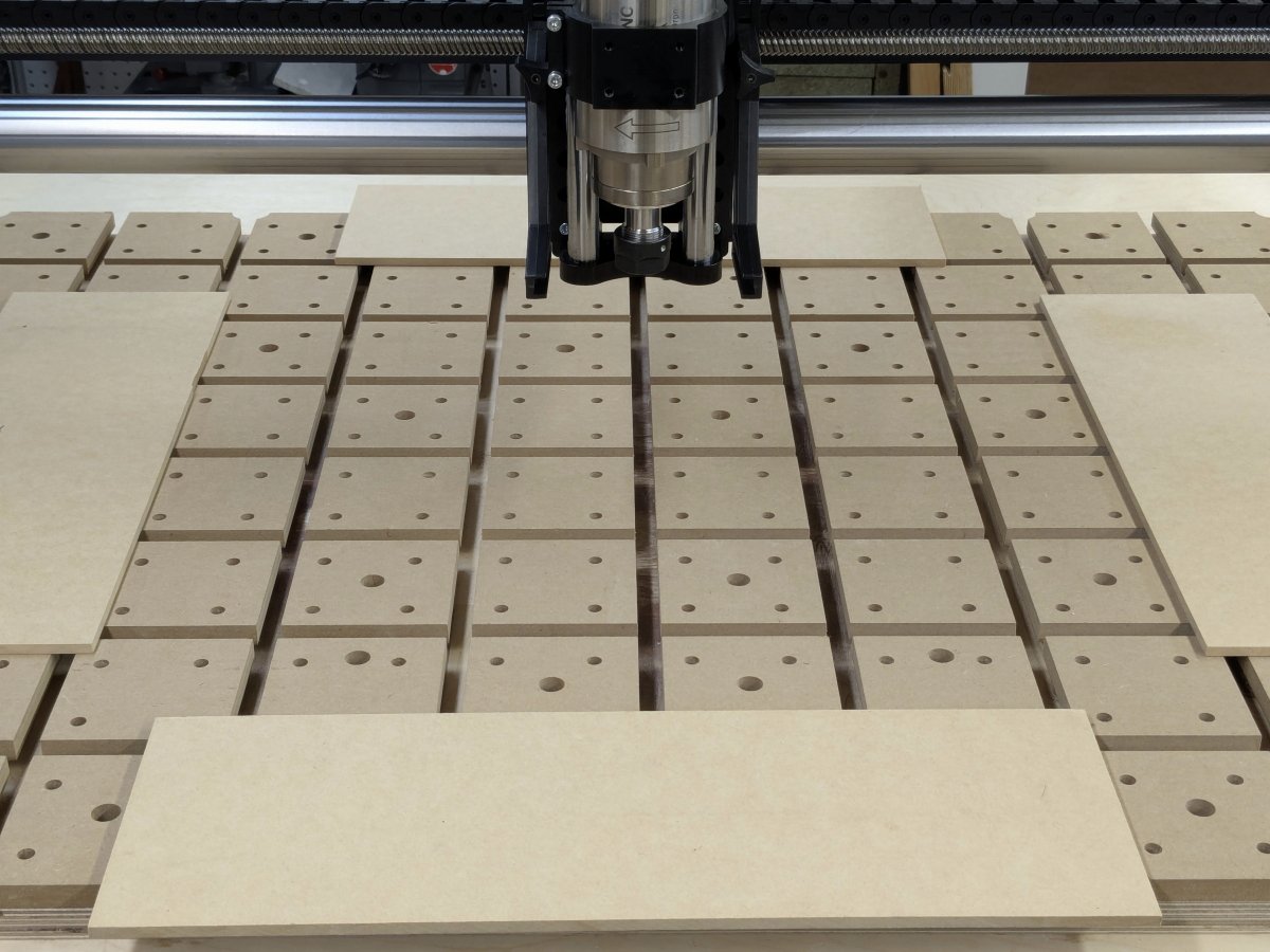
- Simulated frame.JPG (157.65 KiB) Viewed 63225 times
For scale, that's a 4" fixturing grid on the spoilboard. Below is a shot with the 12 mm specimen in place atop the spacers.
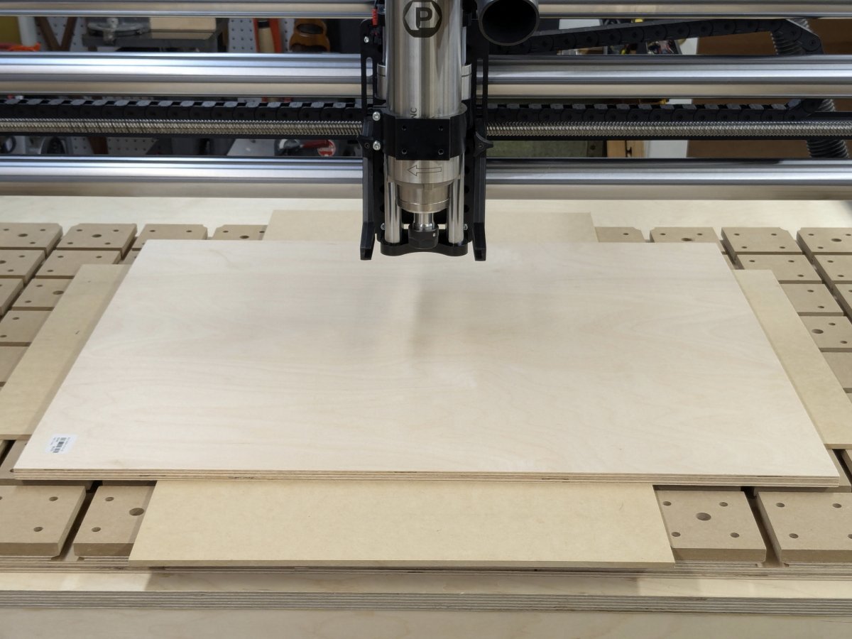
- 12 mm test specimen.JPG (142.2 KiB) Viewed 63225 times
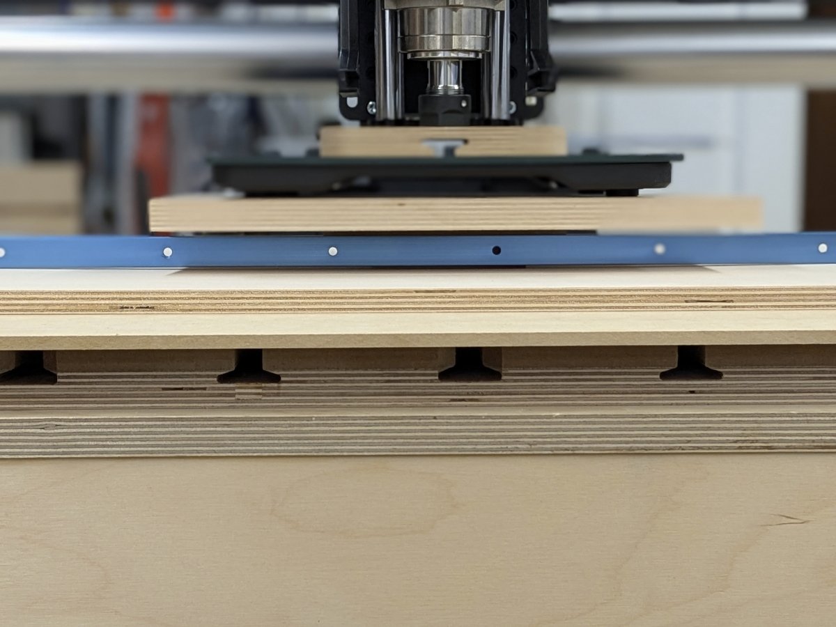
Next, I placed a small pressure pad on the center of the test specimen. The blue rod in the photo below is a 24" long piece of T-track that I placed on its side to use as a compact straightedge. The pressure pad is taller than the T-track, so the track is merely lying on the test specimen, even under maximum test load.
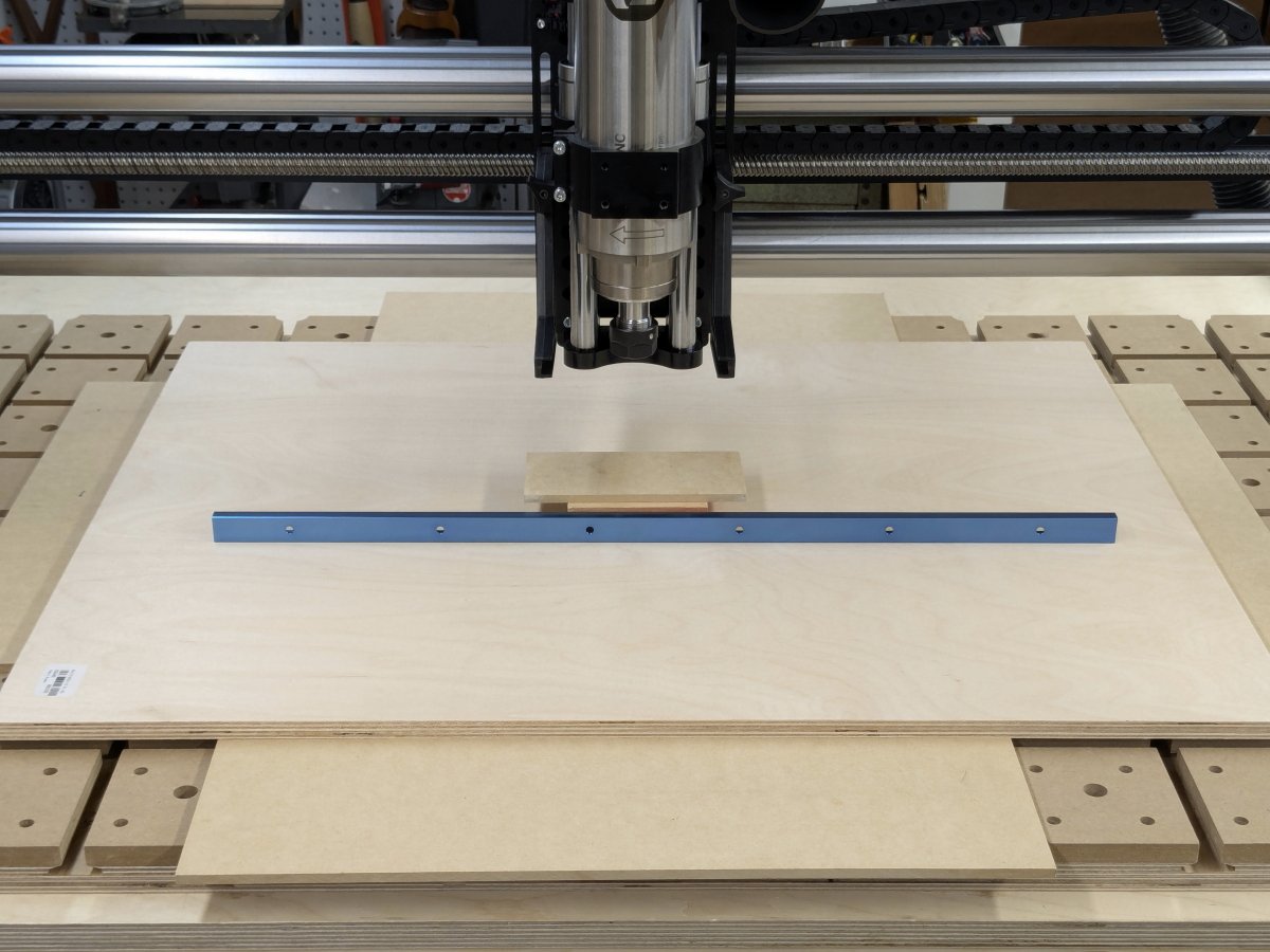
- Pressure pad and straightedge.JPG (149 KiB) Viewed 63225 times
An ordinary digital bathroom scale served as the instrumentation for these experiments. To deal with its rather large footprint, I stacked a piece of 18 mm BB plywood on top of the pressure pad, to serve as a base for the scale. Then I placed another scrap piece of 18 mm plywood on top of the scale, to spread the force from the CNC spindle so as to not break the glass top of the scale.
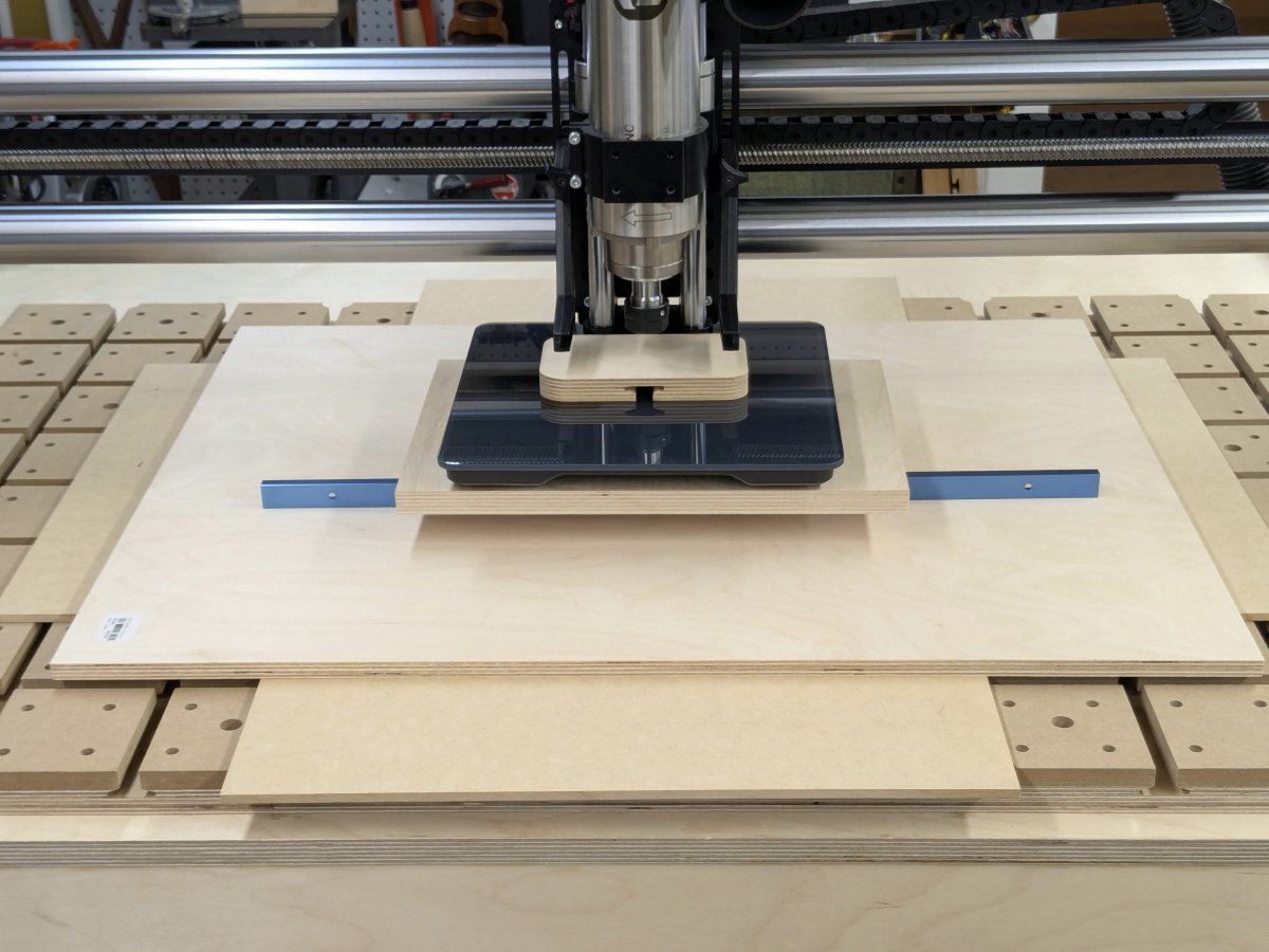
- Scale on platform with pad.JPG (149.8 KiB) Viewed 63225 times
To apply the test loads, I simply lowered the spindle until its collet nut pressed on that top pad with the desired force. I tested both specimens at 50 lb. and 100 lb. Below is a photo that shows the deflection of the 18 mm specimen under a 100 lb. load.
- 12 mm specimen at 100 lb.JPG (137.75 KiB) Viewed 63225 times
To quantify the deflection, I simply measured the gap between the top of the test specimen and the bottom of the straightedge, using setup blocks and/or feeler gauges.
And the deflection results are:
- 12 mm plywood @ 50 lb. load: 0.045"
- 12 mm plywood @ 100 lb. load: 0.087"
- 1/4" plywood @ 50 lb. load: 0.156"
- 1/4" plywood @ 100 lb. load: > 0.25" (my spacers were only 1/4" tall, and the specimen bottomed out on my spoilboard)
Given my shallow drawers and the need for close drawer spacing, I don't want the drawer bottoms to sag by more than 1/8" under full load. The 1/4" plywood fails that standard at even a 50 lb. load, whereas the 1/2" plywood has a good safety margin with a 100 lb. load.
So it appears that you guys have been giving me sound advice!