I'm back and I owe everybody an update on my potentiometer shaft repair.
The NOS potentiometer I ordered showed up and I immediately realized it wouldn't work. The shaft is too short. It was the right style of potentiometer, but the shaft was so short it was hardly any longer than the broken original shaft. So I went back to square one.
It finally dawned on me that the Atari 2600 console from the late 70s/early 80s had paddle controllers with similar potentiometers. Lucky me, I had collected a bunch of these from a garage sale last year which I fixed up and gave out as Christmas gifts to the older generation in my family. Among my big box of Atari parts were non-functional paddle controllers, perfect for parts pirating.
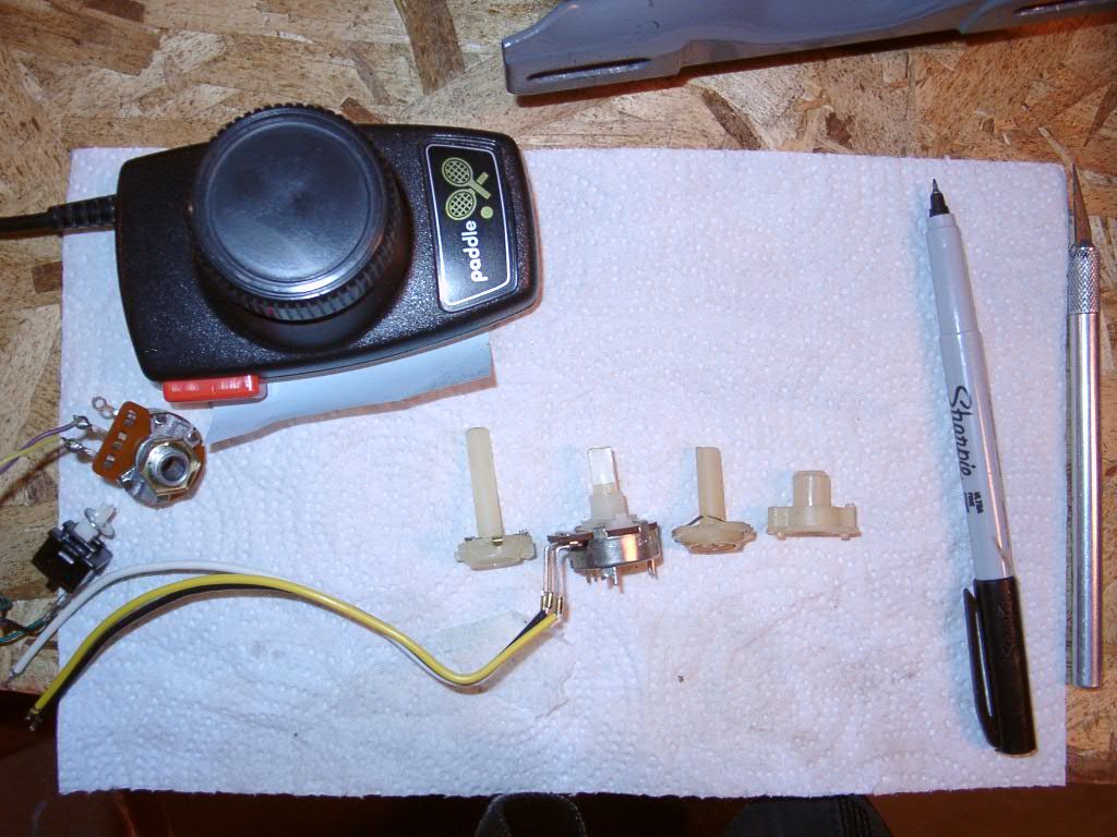
Here is a photo of the Atari paddle controller shaft next to the NOS potentiometer I purchased and also next to the broken original:
The Atari paddle potentiometer shaft isn't an exact replacement, but its close enough. The one thing I changed/modified is to cut away the limit stop to match the original speed controller adjustment range. The next two photos shows the limit stop differences between the Atari shaft with the original (note: the vice grips are NOT marring the shafts, just holding them so I can take the picture):
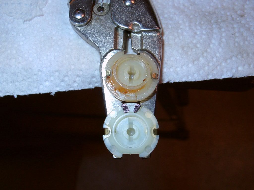
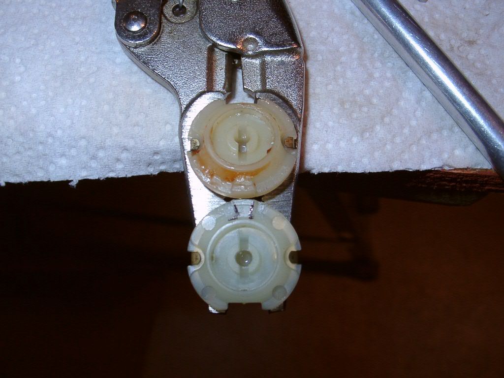
I used an x-acto to carve away the nylon limit stop at the spot highlighted by a black sharpie. This was not hard to do.
After that I put the Atari shaft into the original potentiometer housing and closed it all up. Here is a photo showing the Atari shaft in the controller (the bushing is in backwards here, by the way, but that will be fixed later):
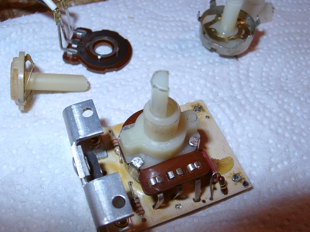
Things seemed smooth enough with the potentiometer check, and the ohm meter confirmed it was working, So I soldered the PCB back onto the wires and proceeded with the power on tests.
Went to hit the switch and it immediately flashed with a loud pop and smoke was released. Then nothing. Dang.

Unplugged it and started the troubleshooting. First I notice that the rectifier is now showing a short between its input terminals. The DIAC and TRIAC are also showing a short from inputs to outputs. What the devil happened????
Well I took the potentiometer apart again and found this:
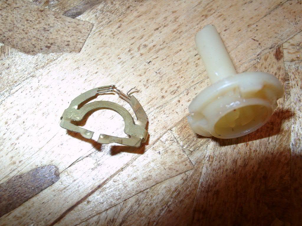
I must have bent the very delicate brush wire upon installation of the Atari shaft. I didn't notice this happening. The bent brush wire then contacted the potentiometer housing. If you've been following along with my posts on this subject, then you should remember that the potentiometer housing is used to bridge the hot input over to the TRIAC. So the full AC line voltage was applied to the DIAC/TRIAC control input pin. The sudden pulse was strong enough to cause the rectifier to also fail.
Now I have the same situation as tdubnik had that started this thread

The bottom of my PCB had vaporized part of the output trace from the TRIAC over to the inductor. That small/thinner portion of the trace conductor must have been designed as a fuse of sorts. If you go back to dusty's photos you can see the thinned down portion of the trace connected to the TRIAC output pin. I didn't have that trace anymore on my damaged board.
This is why I've been away from the topic for the last two weeks. At least I know what to do to fix this thing.
First, I took the good undamaged brush from the original potentiometer shaft and swapped it with the bent Atari brush that shorted to the housing. Then I carefully put the potentiometer back together and made sure it didn't bend a second time. I also checked for shorts to the housing this time around, which is something I should have done the first time knowing that the housing was hot by design.
Second, I ordered a new DIAC, TRIAC and went to my local Radio Shack (which didn't get closed) and picked up a new rectifier module. While I was out shopping I had the additional idea to add a fuse to this circuit. Unfortunately, the only fuse holder that would fit was an automotive style. But I think I can get a regular fuse to fit the automotive fuse holder.
Here is the rectifier and fuse holder I purchased:
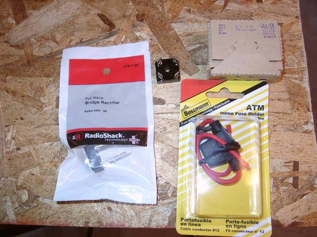
The rectifier is the same exact size as the original, but it has different leads. I trimmed down the leads and soldered the wires to it. The fuse holder was put in place of the white/black stripe wire that connected the control board with the rectifier. Here is a shot of the fuse holder in the controller box:
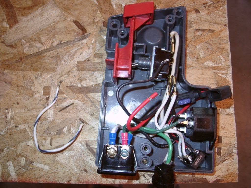
The red wire is the new fuse holder connection that replaced the white/black original wire. Yes, there is an automotive fuse in the fuse holder, but I replaced that with a standard 3 Amp 250V AC fuse in the next photo.
Once the DIAC and TRIAC showed up in a second parts order, I repaired the control board. To repair the vaporized trace, I used one of the cut leads from the rectifier module. That was just the right size to solder onto the bottom of the PCB to make a new connection for the TRIAC output.
Here is a photo of where things stand now:

The NTE DIAC is the same as a DB3 DIAC that are sold for cheap on ebay. I tested these and they had breakover voltage of 32 Volts. That's a bit lower than I originally measured before I blew up my board, but its within the tolerances for these parts (32 +/- 4V).
The proper fuse was used by soldering the leads from an automotive fuse to the glass AC fuse. Its a tight fit, but the rubber cover does close over the assembly. I may try a different way of mounting the fuse as I found soldering the blades to the fuse contacts with the correct alignment to be a bother.
Everything is working again after this ordeal. I'm now going to make some measurements of my DC feed motor speeds and compare that with the published feed rates that the planer is supposed to have. Its my understanding that there are two different feed ranges between different models of the planer.
I have the stand to mount the planer by itself with the 17 amp cutter head motor and the different pulley size upgrade. Now I'm wondering what speeds/feeds I should have given my setup. Figuring out that part is next task.
Sorry for the long post. Hope its helpful for other planer owners in the future.