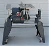
judaspre1982 wrote:Hi John, here are some photos I have and I would be glad to take more if you need them. Only one photo shows the under side of the table but you will get the basic idea.[ATTACH]4193[/ATTACH]
[ATTACH]4194[/ATTACH]
[ATTACH]4195[/ATTACH] I used 1in alum angle for mounting the extension table legs to the main table. I used all the the main tables original mounting wholes that were cast into the table. Once I mounted the angle that runs parallel to the way tubes I cut the angles that run perpendicular to fit snug between them. These are what I mounted the table tubes to. Before drilling the wholes for mounting the tubes to the perpendicular angles I mounted the aux table tubes in the machine ,put the aux main table on top of the tubes mounting bracket, then slid the main table mounted in the carriage over so the two main tables were at the same height and butted the two edges together. This was just a starting point for alignment. I marked the perpendicular angles for mounting whole placement thru the wholes in the aux mounting bracket from underneath while everything was temporarily mounted. Once the position of the holes were marked, I drilled slightly larger holes in the angle to aid in final alignment. The aux table mounting brackets mounting holes are oblong for helping alignment also. Once everything was drilled and mounted loosely, I took the main table out of the carriage. To align the miter slot, I mounted the sanding disc , slid the carriage as far as it would go to the right. and extended the quill so the sanding disc almost touched the edge of the aux main table. From there I used the the miter gauge and a long hex key to get the miter slot square to the sanding disc. I also used several squares to double check everything. It took several tries with shims to get everything adjusted to the main table height wise so the aux table did not have a lean at any of the corners. A good heavy straight edge laid across the top of the two table helps this task. I used all 1/4 - 20 hardware for mounting. Bill Mayo has an aux main table mounted so you can tilt the table also but that requires welding aluminum. Mine only adjusts up and down but was well worth the effort to get greater ripping and cross cutting support and capacity. I hope this makes sense to you, I am not good at explaining things sometimes. If you need any more info let me know---Dave
1955 MK V Restoration Pics
Moderator: admin
Main 500 Table Other Uses
I like your solution too. It looks just like my solution for using the 500 main table on the bandsaw except I had to do some notching on the back cross piece to clear the bandsaw frame.
Bill Mayo bill.mayo@verizon.net
Shopsmith owner since 73. Sell, repair and rebuild Shopsmith, Total Shop & Wood Master headstocks, SPTs, attachments, accessories and parts. US Navy 1955-1975 (FTCS/E-8)
Shopsmith owner since 73. Sell, repair and rebuild Shopsmith, Total Shop & Wood Master headstocks, SPTs, attachments, accessories and parts. US Navy 1955-1975 (FTCS/E-8)
-
judaspre1982
- Platinum Member
- Posts: 1237
- Joined: Tue Jul 08, 2008 10:10 pm
=============================
Last edited by judaspre1982 on Sat May 20, 2017 9:41 am, edited 1 time in total.
-
dusty

- Platinum Member
- Posts: 21530
- Joined: Wed Nov 22, 2006 6:52 am
- Location: Tucson (Wildcat Country), Arizona
[ATTACH]4293[/ATTACH]
Thanks for the idea, Dave. I had an extra Main Table but I now have an Extension Table with two miter tracks.
judaspre1982 wrote:Hi John, here are some photos I have and I would be glad to take more if you need them. Only one photo shows the under side of the table but you will get the basic idea.[ATTACH]4193[/ATTACH]
[ATTACH]4194[/ATTACH]
[ATTACH]4195[/ATTACH] I used 1in alum angle for mounting the extension table legs to the main table. I used all the the main tables original mounting wholes that were cast into the table. Once I mounted the angle that runs parallel to the way tubes I cut the angles that run perpendicular to fit snug between them. These are what I mounted the table tubes to. Before drilling the wholes for mounting the tubes to the perpendicular angles I mounted the aux table tubes in the machine ,put the aux main table on top of the tubes mounting bracket, then slid the main table mounted in the carriage over so the two main tables were at the same height and butted the two edges together. This was just a starting point for alignment. I marked the perpendicular angles for mounting whole placement thru the wholes in the aux mounting bracket from underneath while everything was temporarily mounted. Once the position of the holes were marked, I drilled slightly larger holes in the angle to aid in final alignment. The aux table mounting brackets mounting holes are oblong for helping alignment also. Once everything was drilled and mounted loosely, I took the main table out of the carriage. To align the miter slot, I mounted the sanding disc , slid the carriage as far as it would go to the right. and extended the quill so the sanding disc almost touched the edge of the aux main table. From there I used the the miter gauge and a long hex key to get the miter slot square to the sanding disc. I also used several squares to double check everything. It took several tries with shims to get everything adjusted to the main table height wise so the aux table did not have a lean at any of the corners. A good heavy straight edge laid across the top of the two table helps this task. I used all 1/4 - 20 hardware for mounting. Bill Mayo has an aux main table mounted so you can tilt the table also but that requires welding aluminum. Mine only adjusts up and down but was well worth the effort to get greater ripping and cross cutting support and capacity. I hope this makes sense to you, I am not good at explaining things sometimes. If you need any more info let me know---Dave
Thanks for the idea, Dave. I had an extra Main Table but I now have an Extension Table with two miter tracks.
- Attachments
-
- P4290016.JPG (149.49 KiB) Viewed 12884 times
"Making Sawdust Safely"
Dusty
Sent from my Dell XPS using Firefox.
Dusty
Sent from my Dell XPS using Firefox.
-
JPG

- Platinum Member
- Posts: 35600
- Joined: Wed Dec 10, 2008 7:42 pm
- Location: Lexington, Ky (TAMECAT territory)
Something tells me the price of used main tables is going up on e-bay!:p
╔═══╗
╟JPG ╢
╚═══╝
Goldie(Bought New SN 377425)/4" jointer/6" beltsander/12" planer/stripsander/bandsaw/powerstation /Scroll saw/Jig saw /Craftsman 10" ras/Craftsman 6" thicknessplaner/ Dayton10"tablesaw(restoredfromneighborstrashpile)/ Mark VII restoration in 'progress'/ 10E[/size](SN E3779) restoration in progress, a 510 on the back burner and a growing pile of items to be eventually returned to useful life. - aka Red Grange
╟JPG ╢
╚═══╝
Goldie(Bought New SN 377425)/4" jointer/6" beltsander/12" planer/stripsander/bandsaw/powerstation /Scroll saw/Jig saw /Craftsman 10" ras/Craftsman 6" thicknessplaner/ Dayton10"tablesaw(restoredfromneighborstrashpile)/ Mark VII restoration in 'progress'/ 10E[/size](SN E3779) restoration in progress, a 510 on the back burner and a growing pile of items to be eventually returned to useful life. - aka Red Grange
-
judaspre1982
- Platinum Member
- Posts: 1237
- Joined: Tue Jul 08, 2008 10:10 pm
=======================
Last edited by judaspre1982 on Fri May 19, 2017 4:19 pm, edited 1 time in total.
-
horologist

- Gold Member
- Posts: 431
- Joined: Sat Dec 22, 2007 6:36 pm
- Location: Melrose, FL
-
judaspre1982
- Platinum Member
- Posts: 1237
- Joined: Tue Jul 08, 2008 10:10 pm
==========================
Last edited by judaspre1982 on Fri May 19, 2017 4:14 pm, edited 1 time in total.
-
JPG
- Platinum Member
- Posts: 35600
- Joined: Wed Dec 10, 2008 7:42 pm
- Location: Lexington, Ky (TAMECAT territory)
It appears your Greenie has the speed control/switch interlock(or whatever its purpose is). It also appears it is no longer functional since it looks like an alternate switch has been installed.
Do know how the linkage going up to the original power switch is interfaced with the speed control dial? Does it somehow use the groove on the back side of the dial which runs from lo speed up to about saw/joint but stops b4 rout?
Do know how the linkage going up to the original power switch is interfaced with the speed control dial? Does it somehow use the groove on the back side of the dial which runs from lo speed up to about saw/joint but stops b4 rout?
╔═══╗
╟JPG ╢
╚═══╝
Goldie(Bought New SN 377425)/4" jointer/6" beltsander/12" planer/stripsander/bandsaw/powerstation /Scroll saw/Jig saw /Craftsman 10" ras/Craftsman 6" thicknessplaner/ Dayton10"tablesaw(restoredfromneighborstrashpile)/ Mark VII restoration in 'progress'/ 10E[/size](SN E3779) restoration in progress, a 510 on the back burner and a growing pile of items to be eventually returned to useful life. - aka Red Grange
╟JPG ╢
╚═══╝
Goldie(Bought New SN 377425)/4" jointer/6" beltsander/12" planer/stripsander/bandsaw/powerstation /Scroll saw/Jig saw /Craftsman 10" ras/Craftsman 6" thicknessplaner/ Dayton10"tablesaw(restoredfromneighborstrashpile)/ Mark VII restoration in 'progress'/ 10E[/size](SN E3779) restoration in progress, a 510 on the back burner and a growing pile of items to be eventually returned to useful life. - aka Red Grange
-
judaspre1982
- Platinum Member
- Posts: 1237
- Joined: Tue Jul 08, 2008 10:10 pm
RE: Stop Spring
=====================
Last edited by judaspre1982 on Fri May 19, 2017 4:13 pm, edited 1 time in total.