Dusty -- Yes, the SS rail connecting tubes must be very straight. Even then, because of the loose fit of the tubes within the rail you may still experience some misalignment when tightening the sliding miter table (SMT) mount to the tube. It's possible when tightening one of the SMT mounts that you could force the table out of alignment. When I had the SMT mounted on my SS 520 I made a habit of keeping a square handy to check alignment of the miter bar to the blade. Surprisingly I maintained pretty close alignment most of the time... even following relocation of the SMT.
Because of the above issues I decided to incorporate the BT3000 one-piece rails on my SS... that eliminates most alignment issues when using the SMT.
Ron
Sliding Miter Table
Moderator: admin

Oh that's just great..... Ryobi BT3000
That's one more thing to look for on CL every day.
Yesterday I didn't even know what one was... Today I gotta have one.
All joking aside though Very Nice job worknhard! sweeeet
That's one more thing to look for on CL every day.
Yesterday I didn't even know what one was... Today I gotta have one.
All joking aside though Very Nice job worknhard! sweeeet
Bruce
I didn't know what a Shopsmith was...
Three days later I owned one...
One week later I was rebuilding one...
Four months later I owned two....
Ok Ok, I'm up to four now...
I didn't know what a Shopsmith was...
Three days later I owned one...
One week later I was rebuilding one...
Four months later I owned two....
Ok Ok, I'm up to four now...
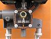
A bit more progress on my adapter to the 510 while keeping the SS tubes: I found that galvanized 3/4" iron pipe (a little over 1" O.D.) just slides into the 510 pipe rails so I got two pieces about 14" long. Some 3/4" pipe is just a bit too big and would have to be turned down a few thousandths in a lathe, but the pieces I got were "just right". It will be held firmly by the usual knurled jackscrew (part 145 on the exploded 510 parts diagram).
I then cut the "Z" piece (a 2.25" leg, 1" center, 4" leg, approximately) to drop the Ryobi table out of 2" x 3/8" aluminum flat bar as seen here:
[ATTACH]18746[/ATTACH]
I ground the short leg by eye on a coarse belt sander to be a tight fit in the pipe. I had to tap it home with a hammer. Here is the assembled pipe with "Z" piece. I made two of them, of course.
[ATTACH]18747[/ATTACH]
I intend to bolt a short piece of angle to the "Z" piece that is adjustable for height to raise the table flush with the SS one. Please excuse the crappy drawing.
[ATTACH]18749[/ATTACH]
The next photo shows the sliding table sitting low without that angle ( assembled in rough position just for the photo, to give some idea of what I mean). I hope to make the angles in the next day or two.
[ATTACH]18748[/ATTACH]
I am hoping this design will allow aligning the sliding table without too much trouble on either the left or right, easy removal and also allow it to be mounted at varying distances away from the SS table. Comments/suggestions welcomed.
- Attachments
-
- IMG_0575.JPG (78.07 KiB) Viewed 55310 times
-
- IMG_0576.JPG (52.1 KiB) Viewed 55291 times
-
- IMG_0577.JPG (31.76 KiB) Viewed 55303 times
-
- angle for levelling.jpg (57.48 KiB) Viewed 55296 times
Peter
a 510,a Mini, dedicated SS drillpress, SS spt's, home made SS belt grinder, SS piston air system, Southbend 10k lathe, mill/drill, Taig
a 510,a Mini, dedicated SS drillpress, SS spt's, home made SS belt grinder, SS piston air system, Southbend 10k lathe, mill/drill, Taig
OOPS: looking at photos above and earlier, discovered a bit of metal needs to be cut off to allow the sliding table to pass:
[ATTACH]18750[/ATTACH]
[ATTACH]18750[/ATTACH]
- Attachments
-
- clearance to table.jpg (42.46 KiB) Viewed 55304 times
Peter
a 510,a Mini, dedicated SS drillpress, SS spt's, home made SS belt grinder, SS piston air system, Southbend 10k lathe, mill/drill, Taig
a 510,a Mini, dedicated SS drillpress, SS spt's, home made SS belt grinder, SS piston air system, Southbend 10k lathe, mill/drill, Taig
-
dusty

- Platinum Member
- Posts: 21481
- Joined: Wed Nov 22, 2006 6:52 am
- Location: Tucson (Wildcat Country), Arizona
prmindartmouth wrote:A bit more progress on my adapter to the 510 while keeping the SS tubes: I found that galvanized 3/4" iron pipe (a little over 1" O.D.) just slides into the 510 pipe rails so I got two pieces about 14" long. Some 3/4" pipe is just a bit too big and would have to be turned down a few thousandths in a lathe, but the pieces I got were "just right". It will be held firmly by the usual knurled jackscrew (part 145 on the exploded 510 parts diagram).
I then cut the "Z" piece (a 2.25" leg, 1" center, 4" leg, approximately) to drop the Ryobi table out of 2" x 3/8" aluminum flat bar as seen here:
[ATTACH]18746[/ATTACH]
I ground the short leg by eye on a coarse belt sander to be a tight fit in the pipe. I had to tap it home with a hammer. Here is the assembled pipe with "Z" piece. I made two of them, of course.
[ATTACH]18747[/ATTACH]
I intend to bolt a short piece of angle to the "Z" piece that is adjustable for height to raise the table flush with the SS one. Please excuse the crappy drawing.
[ATTACH]18749[/ATTACH]
The next photo shows the sliding table sitting low without that angle ( assembled in rough position just for the photo, to give some idea of what I mean). I hope to make the angles in the next day or two.
[ATTACH]18748[/ATTACH]
I am hoping this design will allow aligning the sliding table without too much trouble on either the left or right, easy removal and also allow it to be mounted at varying distances away from the SS table. Comments/suggestions welcomed.
Peter:
Why does the sliding table need to be "aligned" AND to what point of reference would you align?
The sliding table is there primarily as a movable pivot point for the miter fence. The miter fence slides in preformed miter tracks that are part of the base. If the base is snug against the edge of the main table, will that not result in pivot point always being a consistent distance from the blade.
ASSUMPTION: My comments are based on an assumption that the edges of you Main Table are smooth and most importantly "parallel to the miter slots". If this is an invalid assumption, I would start by correcting that.
If you are using a later model Main Table, there are two milled reference points on each side of the Main Table for you to utilize. If this be the case, the above assumption is unnecessary. The sides need not be smooth and parallelism is achieved by the milled reference points. Just snug up against them.
I'm curious as to why you use the tube inside the rail. Is there a reason why your offset fixture could not have been milled so as to fit directly into the rail.
BTW, I think your offset fixture is a very creative way of adapting to the 510 tubes. I also believe that introducing the sliding miter table into the setup will greatly improve overall your mitering experience. The only concern I have is how reliable is the Ryobi pivot point. Does it lock the miter fence in position adequately? If that angle changed midway through a miter cut it could result in a kick back disaster. Please understand that I have NO EXPERIENCE with this sliding table. My comments are those of a practicing skeptic.
"Making Sawdust Safely"
Dusty
Sent from my Dell XPS using Firefox.
Dusty
Sent from my Dell XPS using Firefox.
Dusty, you raise some great points for discussion. I will put my replies in blue:
Peter:
Why does the sliding table need to be "aligned" AND to what point of reference would you align?
I have no experience with sliding tables so I just assumed the Ryobi base will have to be aligned to the main table and the blade. I recently found out that the Ryobi owners manual details a procedure to follow.
The sliding table is there primarily as a movable pivot point for the miter fence. The miter fence slides in preformed miter tracks that are part of the base. If the base is snug against the edge of the main table, will that not result in pivot point always being a consistent distance from the blade.
Yes, I agree, but I cannot get the base against the edge of the SS table as you might see in my second last photo above. Instead I was thinking I would set it using a spacer block .I actually used a drill bit
ASSUMPTION: My comments are based on an assumption that the edges of you Main Table are smooth and most importantly "parallel to the miter slots". If this is an invalid assumption, I would start by correcting that.
If you are using a later model Main Table, there are two milled reference points on each side of the Main Table for you to utilize. If this be the case, the above assumption is unnecessary. The sides need not be smooth and parallelism is achieved by the milled reference points. Just snug up against them.OK, thanks, I will look for the reference points.I do not have milled ref. points unfortunately, so I used the miter slot for now.
I'm curious as to why you use the tube inside the rail. Is there a reason why your offset fixture could not have been milled so as to fit directly into the rail. Yes, it could have been but I thought it would have had to be more than 3/8" thick. I wanted a snug fit that was removable and that would also let the sliding table be mounted some distance out from the main table. Using the tube inside the rail seemed easier than making a "Z" piece with one long leg that was made to just fit smoothly into the rail. Using the tube also lets me secure with the jack screw.Today I found the pipes are very tight in the 510 rail tubes so I have some work to do if I want the sliding table to be easily removable.
BTW, I think your offset fixture is a very creative way of adapting to the 510 tubes. I also believe that introducing the sliding miter table into the setup will greatly improve overall your mitering experience. The only concern I have is how reliable is the Ryobi pivot point. Does it lock the miter fence in position adequately? If that angle changed midway through a miter cut it could result in a kick back disaster. Please understand that I have NO EXPERIENCE with this sliding table. My comments are those of a practicing skeptic.Dusty, your comments are much appreciated and I will be on the alert for angle change. It seems quite solid but a friend who has had a BT3000 for 10 years says he is careful to clamp his work piece to the fence and to push the fence so as to not disturb its setting. I think you have alerted me to a potential safety issue and I will follow up with my friend.
Peter
a 510,a Mini, dedicated SS drillpress, SS spt's, home made SS belt grinder, SS piston air system, Southbend 10k lathe, mill/drill, Taig
a 510,a Mini, dedicated SS drillpress, SS spt's, home made SS belt grinder, SS piston air system, Southbend 10k lathe, mill/drill, Taig
Scrounging around in my junk, I found some (well) used aluminum angle and got the table mounted on my 510 today:
[ATTACH]18753[/ATTACH]
These next two are looking up at the supports.
[ATTACH]18754[/ATTACH]
[ATTACH]18755[/ATTACH]
I have to spend some time getting it leveled and lined up with the SS. After some tweaking, I think it is going to be a nice addition.
Apologies to Ron (worknhard) for butting into his thread and many thanks for the idea!!
- Attachments
-
- IMG_0578.JPG (85.16 KiB) Viewed 55278 times
-
- IMG_0579.JPG (44.25 KiB) Viewed 55218 times
-
- IMG_0580.JPG (76.58 KiB) Viewed 55220 times
Peter
a 510,a Mini, dedicated SS drillpress, SS spt's, home made SS belt grinder, SS piston air system, Southbend 10k lathe, mill/drill, Taig
a 510,a Mini, dedicated SS drillpress, SS spt's, home made SS belt grinder, SS piston air system, Southbend 10k lathe, mill/drill, Taig
Peter -- No apologies needed... I like your design and think it's a very creative solution for adapting the BT3 SMT to the 510 system. Couple questions; 1. how do you lock/secure your SMT mount within the 510 tubes? It appears that tube part of your mount slides into the 510 fence rail, but how does it stay in place? 2. Do you have a system for squaring your SMT and miter bar with the SS table and blade? 3. I noticed that you installed a fastener (bolt and nut) across one track of the SMT base to act as a stop for the sliding table... Was there a particular reason for this instead of keeping the original BT3 sliding stop arrangement? By using a fastener across the track you may be reducing the amount of table travel -- I'm guessing by about 6". That means the max size of the workpiece that you are cross-cutting is reduced by about 6".
Regarding concerns about the miter bar slipping or moving when performing a cross-cut, that shouldn't be a problem. Once you set the angle and tighten the miter bar knob, it stays in place. You should however have the pivot peg inserted in the table. If you are cross-cutting long boards I would advise using the "long miter" bar that Ryobi has. It is about 36" long and provides a much more stable bar for cutting wide/long pieces. There is also a miter clamping kit that you can buy to help secure the workpiece, but you usually don't need it... if fact I don't think I have ever used mine... it came with my BT3000 saw when I got it in 94.
Thanks for sharing info on your mod.
Ron
Ron, thanks for your reply. 1.I lock the pipe in the 510 rail using the jack screws- part 145 on the SS exploded parts diagram. 2. I do not yet have a system for squaring the SMT and miter bar with the SS table and blade. That is something to sort out before using the SMT. There should be plenty of adjustments in my mounting plus the 4 bolts from the guide to my angles. Page 31 in the Ryobi manual covers Checks and Adjustments and should be a good guide. 3. I put in the stop bolts because after removing the original cam lock assemblies which are no longer used on the 510, the original stops were gone too. Regarding " the max size of the workpiece that you are cross-cutting is reduced by about 6" "I have about 14" from the fence to the end of the SS blade slot, so the work piece can be about 15" max, as seen here:
[ATTACH]18756[/ATTACH]
What is your dimension here?
I do have the long fence you refer to. I actually bought the table with a BT3000 for $100 and two days later, another more complete BT3000 with a bad motor for $40, so I kept one table and long fence and made up one nice complete saw from the remaining parts that I sold for $175.......worked out great for me!
- Attachments
-
- workpiece size.jpg (82.86 KiB) Viewed 55207 times
Peter
a 510,a Mini, dedicated SS drillpress, SS spt's, home made SS belt grinder, SS piston air system, Southbend 10k lathe, mill/drill, Taig
a 510,a Mini, dedicated SS drillpress, SS spt's, home made SS belt grinder, SS piston air system, Southbend 10k lathe, mill/drill, Taig