Page 4 of 6

Re: A serious challenge

Posted: Wed Jan 13, 2016 7:14 am
by algale
BuckeyeDennis wrote:Al, I think I followed what you were proposing. But what is to prevent someone from simply opening all of the drawers, and thereby unlocking the "special" drawer?
Ooops. :o Back to the drawing board! I'm not OCD enough to think of opening all the drawers at once. Or maybe I'm too OCD to do that!

Re: A serious challenge

Posted: Wed Jan 13, 2016 7:25 am
by BuckeyeDennis
algale wrote:
BuckeyeDennis wrote:Al, I think I followed what you were proposing. But what is to prevent someone from simply opening all of the drawers, and thereby unlocking the "special" drawer?
Ooops. :o Back to the drawing board! I'm not OCD enough to think of opening all the drawers at once. Or maybe I'm too OCD to do that!
You're in good company. As Jimmy Buffet says, "Indecision may or may not be my problem." :D

Re: A serious challenge

Posted: Wed Jan 13, 2016 9:46 am
by Beave2012
algale wrote:
BuckeyeDennis wrote:Al, I think I followed what you were proposing. But what is to prevent someone from simply opening all of the drawers, and thereby unlocking the "special" drawer?
Ooops. :o Back to the drawing board! I'm not OCD enough to think of opening all the drawers at once. Or maybe I'm too OCD to do that!
I like the ease of your solution and it will work, but you need to tweak the solution.
- you need two independent panels, so that you can have a slot next to the panel that doesn't interfere with the locking panel.
- next you will need two hooks, one for each panel to lock it (unless you don't use a full column.
- you then run a tab on the back side of the non-reliant drawers. That tab slides into the slots next to the panel.
- the key is that those slots hold a button that when pressed remove a dowel from behind the panel. That way they need to be in to allow vertical movement of the panel. (key drawers lock when in, non-keys lock when out)
-the buttons for non-keys drawers is a simple horseshoe shape with spring loaded pin (small enough you could use Springs from pens).
-the relocking hole could have a bar placed so that a single touch lifts both sides at once. Although it should be a recessed button trimmed flush so no one can look inside.

Hope that helps.

Re: A serious challenge

Posted: Wed Jan 13, 2016 11:53 am
by JPG
BuckeyeDennis wrote:Al, I think I followed what you were proposing. But what is to prevent someone from simply opening all of the drawers, and thereby unlocking the "special" drawer?
Nuttin! :D

+AND function 'solved'!

-OR function remains. ;)

Re: A serious challenge

Posted: Wed Jan 13, 2016 6:00 pm
by BuckeyeDennis
I think I have a concept that is feasible to build. After contemplating sliding mechanisms for a while, I started wondering if it could be done with pinned/rotating joints instead. I believe it can.

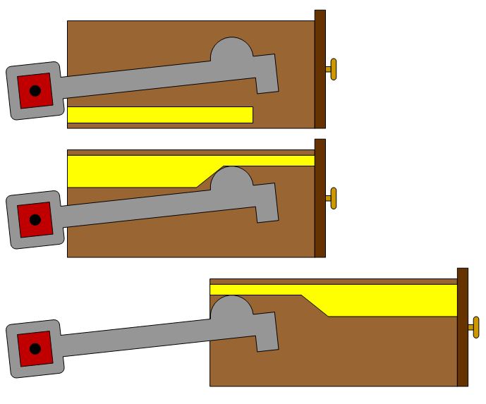
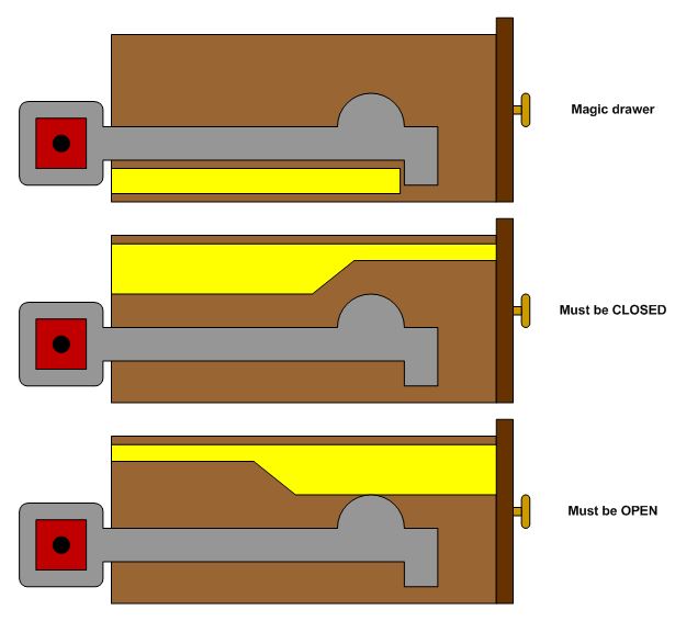
Basically, each row of drawers has an associated “drive bar” which spans the entire row, and all of the drive bars rotate in unison. Each drawer has an associated “actuator” which is rotated by the drive rod. The actuators are all identical, but each drawer is programmed as “Must be OPEN”, “Must be CLOSED”, or “Magic Drawer” by installing the appropriate “key” on the drawer. The magic drawers, of course, are the ones that are unlocked by moving all the other drawers into the appropriate position.
Unlocked without linkage.JPG
Unlocked without linkage.JPG (39.83 KiB) Viewed 3408 times
In the illustration above, we see a side view of a column of drawers. The red squares are the drive rods, seen from their end, and they rotate about the carcase-mounted pins shown in black. We’ll add a parallelogram linkage later, so that all the drive rods rotate in unison. The grey things are the actuators, and they are shown square-drive keyed onto the drive rods. The yellow things are the keys. They are fastened to the side of the drawer box, and they determine the behavior of the drawers. I envision both the actuators and keys being quite thin – perhaps 1/8” or so, depending on material selection.

I placed the keys on the sides of the drawer boxes because that is where I think they can be packaged into the smallest space. So the drawer slides (perhaps dovetail slides) would have to go on the bottom of the drawer.

It’s not shown in the illustration, but I’d put a cover plate on the outside of the keys, for two reasons. One, it would capture the actuator side-to-side. Thus the actuator can simply float on the drive rod, minimizing any tolerance issues. Two, it would hide the key, so someone can’t figure out the code simply by opening the drawers and inspecting all the keys.

The next illustration shows all the drawers in the position that unlocks the magic drawer. In these positions, no key will block its associated actuator from lifting, and so a spring or counterweight will rotate the drive rods counterclockwise, lifting all the actuators and unlocking the magic drawer. But if even one drawer is in the wrong position, the drive rods can’t rotate, and the magic drawer stays locked.
Locked without linkage.JPG
Locked without linkage.JPG (39.13 KiB) Viewed 3408 times
This design has a few bonus features:
1) There is no restriction on the number of rows or columns of drawers. As a matter of fact, the drawers do not even have to be in regular columns.
2) You can “program” the drawers in any combination you want. You can even have multiple “magic drawers”.
3) You can program a drawer as a “Don’t Care” by not installing any key.
4) If you want, you can design keys with additional behaviors. For example, you could key a drawer such that it has to be half-open in order to unlock the magic drawer(s).
5) This one may or may not be a “bonus”. But as designed, the code is determined by the drawers themselves. Suppose that each drawer was labeled with a letter. You could shuffle the drawers about (swapping them into different cubbies) as much as you like, but the letter code would not be changed by this shuffling.

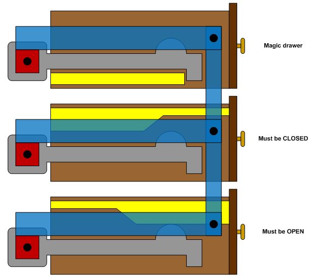
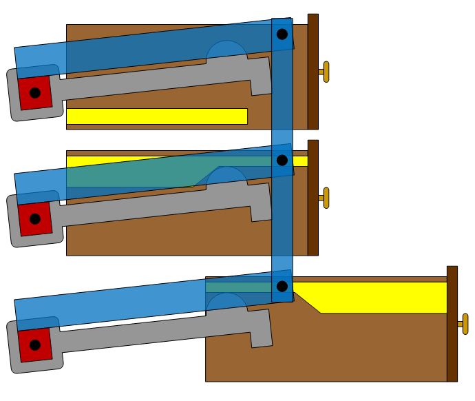
And that’s about it, except for adding the parallelogram linkages to the drive rods. In the illustrations below, I have them shown in blue, oriented toward the front of the carcase. This permits longer links with proportionally better pin-slop tolerance, without having to grow the carcase rearward. I would probably place the parallelogram linkage against the side of the carcase. Possibly on both sides of it, if I was concerned about drive-rod twisting.
Locked with linkage.JPG
Locked with linkage.JPG (44.9 KiB) Viewed 3408 times
Unlocked with linkage.JPG
Unlocked with linkage.JPG (39.14 KiB) Viewed 3408 times
There's lots of ways to skin a cat!

Re: A serious challenge

Posted: Wed Jan 13, 2016 6:07 pm
by algale
Brilliant!

Re: A serious challenge

Posted: Thu Jan 14, 2016 7:20 am
by robinson46176
.
.
.
.
Duct tape...


.

Re: A serious challenge

Posted: Thu Jan 14, 2016 9:38 am
by BuckeyeDennis
It dawned on me last night that my pins-and-levers concept would package better if you flipped the whole shebang by 90 degrees. So the drive bars are now running vertically, up along a column of drawers. This has the following benefits:

1. The keys and actuators can now be hidden inside double drawer bottoms. So the drawer sides are once again thin and symmetrical, and the drawer slides can be mounted either to the drawer sides or to the drawer bottom.
2. Gravitational loading of the linkages is eliminated. Everything moves in a horizontal plane.
3. The parallelogram linkage can now be located either at the top or the bottom of the carcase. Either way, it doesn't increase the width of the unit.

Below are slightly-revised illustrations, each showing a bottom-view of a row of drawers.
Reoriented and locked.JPG
Reoriented and locked.JPG (47.53 KiB) Viewed 3370 times
Reoriented and unlocked.JPG
Reoriented and unlocked.JPG (46.81 KiB) Viewed 3370 times

Re: A serious challenge

Posted: Thu Jan 14, 2016 12:30 pm
by rjent
Dennis, I think that would work....

Slick idea! :cool:

(my idea will work as well, but I ain't painting any pretty pictures to prove it. Besides, I like yours better ... :) )

Re: A serious challenge

Posted: Thu Jan 14, 2016 12:44 pm
by JPG
I do not 'see' the reorientation. Looks like the same pix as before.

I do understand this and really like it! :)