Page 4 of 8
Posted: Sun May 15, 2011 9:45 pm
by jayp413
JPG40504 wrote:Spring looks normal!!!!!!
It was actually broken where it enters the housing. For some reason I put it inplace for the photo


I'll snap a new pic of it broken.
Posted: Mon May 16, 2011 12:15 am
by JPG
jayp413 wrote:It was actually broken where it enters the housing. For some reason I put it inplace for the photo
I'll snap a new pic of it broken.
The right end hooks into the small hole(bent). The left end rides in that groove(straight).
Posted: Mon May 16, 2011 4:55 pm
by jayp413
JPG40504 wrote:The right end hooks into the small hole(bent). The left end rides in that groove(straight).
Ahhh ok. Maybe it is alright then. i assumed the spring was supposed to go through on both sides. thank you sir!

Posted: Mon May 16, 2011 6:58 pm
by JPG
jayp413 wrote:Ahhh ok. Maybe it is alright then. i assumed the spring was supposed to go through on both sides. thank you sir!
The 'coiled' part rides the back of the dial. The back of the dial has a step just beyond 'saw-joint'. The spring rides up that step also. You can feel the added resistance as you adjust upward into the 'step'.
Historically that was a stop that required depressing a pin away from the ramp to increase speed above that setting.(Early Greenies - A Headstock).
Posted: Mon May 16, 2011 11:53 pm
by charlese
Thanks, Red!:) I always wondered why that step existed in the back of the speed dial.
Posted: Tue May 17, 2011 1:40 am
by JPG
charlese wrote:Thanks, Red!:) I always wondered why that step existed in the back of the speed dial.
And I cannot believe some of the kockamamie explanations I have seen/heard.
I really do not think 'anti-rattle' was the original intention. The original 'stop' makes sense and the modified design was IMHO to eliminate the need for two hands(one to press the 'release' and one to turn the crank) while retaining the 'tactile' feedback that indicated the 'stop' was exceeded.
The stop 'pin' was attached to a bracket that mounted under the power switch and the bracket included an arrow that served as an index mark for the speed dial. By pressing down and in on the bracket, the pin moved to clear the stop on the back of the dial.
Posted: Tue May 17, 2011 4:13 am
by jcraigie
I'll post a pic of mine later today
Posted: Wed May 18, 2011 9:15 pm
by jayp413
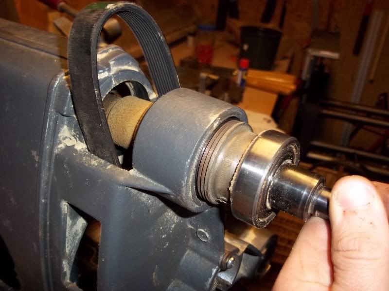
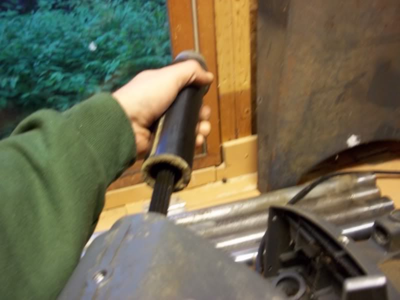
Hit it again tonight for about an hour or so. I started working on the drive sleeve assembly.
Started by removing the retaining ring that holds the drive assembly sleeve in the headstock. I used a flathead screwdriver to pop the ring out. It's hard to see here but it's on the outer edge inside.
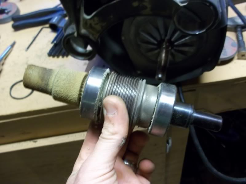
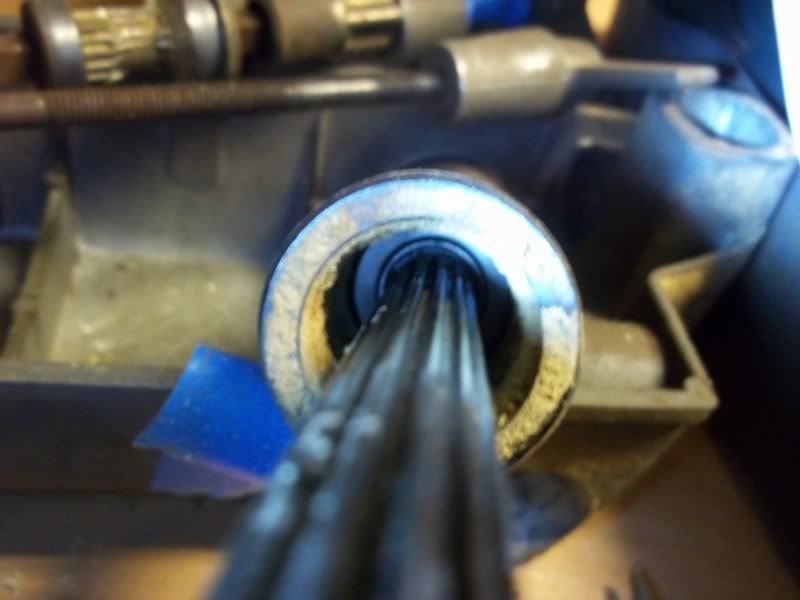
Here is a picture of the spring starting to come out.
 (more in the next post)
Posted: Wed May 18, 2011 9:18 pm
by jayp413
Posted: Wed May 18, 2011 9:21 pm
by jayp413
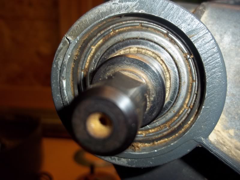
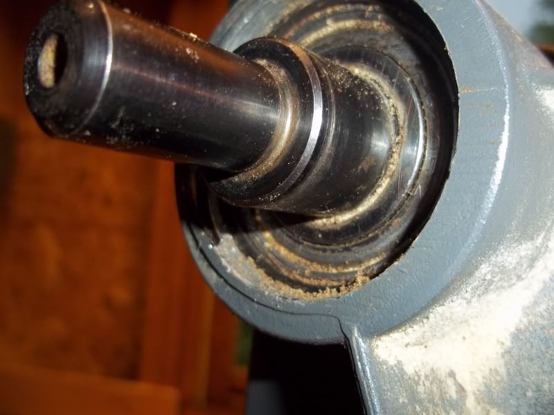
The quill assembly removal was next. I loosened the allen screw ontop of the headstcok and advanced the quill until I felt it disingage and removed it.
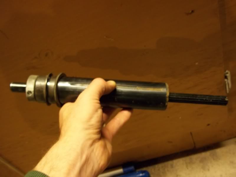
Can anyone tell by the picture if it's a one or two bearing quill/ it looks to be two but i'm not positive.
 (more in next post)