Page 5 of 5
Re: PowerPro just quit ....
Posted: Tue Jul 19, 2016 3:11 pm
by rjent
[quote="BuckeyeDennis"][/quote]
It's funny you bring that up. Jim said they had a design problem with the very same parameters in the beginning. The failure components (almost exclusively) are two caps and that big coil you see in the picture Dusty posted. There are/were clearence problems that cause shorts. He thought he had the design fixed, but maybe not quite yet. Failure rate is very low, so who knows.
In your example above, just like an engineer to blame the tech ....

Re: PowerPro just quit ....
Posted: Tue Jul 19, 2016 3:36 pm
by JPG
rjent wrote:BuckeyeDennis wrote:
It's funny you bring that up. Jim said they had a design problem with the very same parameters in the beginning. The failure components (almost exclusively) are two caps and that big coil you see in the picture Dusty posted. There are/were clearence problems that cause shorts. He thought he had the design fixed, but maybe not quite yet. Failure rate is very low, so who knows.
In your example above, just
like an engineer to blame the tech ....
Not if the engineer is honest with them self.

Re: PowerPro just quit ....
Posted: Tue Jul 19, 2016 4:10 pm
by BuckeyeDennis
Now guys, I did say that I had also missed the error when I reviewed the PCB layout.

Which means there was a
two-point failure in the design process.
The strange thing is, I well remember running test voltages all the way up to 1000V when bench-testing prototypes. So by pure bad luck, the air gap was exactly the wrong size. Too small to be reliable, but too large to fail during bench testing.
Re: PowerPro just quit ....
Posted: Tue Jul 19, 2016 4:33 pm
by reible
Since some of you have interest in this sort of thing........ the caps will have a thin scored area on top with the intent of having it break open there. Normally this appears as three lines from the center out. I found a picture on line of a blown one.
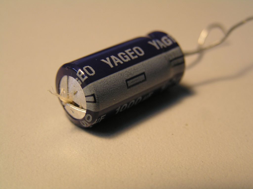
- cap 1.jpg (44.96 KiB) Viewed 3880 times
Some like the ones on the shopsmith are oil filled so when they pop they drip oil. The are also loud, very easy to notice because it is like a firecracker pop.
So the cover not only keeps the dust off it keeps the oil from spraying. Some more expensive caps have a jacket to contain the mess and are always mounted in a certain orientation.
The toroid coil is more likely to have a solder failure because they are often just mounted by the leads and thermal issues can along with weight tend to be hard on the joints. A better design is to mechanically attach the toroid but that is often not done due to needing a carrier and that adds cost.
There are various rtv coatings that can be applied with pretty high voltage break down specks, again added expense so........
Any large leaded devices that have large thermal changes can be a problem and guess what you have in a power supply, yea lot of those parts.
Many years ago when looking at some cheaper PC power supplies with a lot of failures we found that a company was taking a much smaller and less capable cap and put it in a large can so it would look like something that it wasn't. Could not believe people would do that but there they were.
Ed
Re: PowerPro just quit ....
Posted: Fri Jul 22, 2016 7:18 pm
by Shug
It's not necessarily the solder joints that will fail. Thru-hole plating can't accept much stress and the PCB pads themselves can separate from the PCB substrate. A large heavy object cantilevered off of PCB thru-hole (or worse, surface mount) pads that operates in an environment with cyclical loading is a design I'd be really cautious using. Don't forget that copper fatigues, especially when the cyclical stresses are close to its yield strength.
As the solder cools after the components are soldered into the PCB, mechanical stresses are induced that add to the total loading on the pads and thru-hole plating.