johnm wrote:I just caught up with this thread...
It seems that if you measure voltage on the motor brushes and it is wired like you show in the schematic, then it ought to turn. Can you turn it by hand? Make sure it is not binding. If the armature winding (the part the brushes connect to) is open circuit, then it won't run. You can check that with an ohm-meter across the place where the brushes make contact.
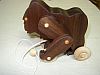
The motor looks like a "universal motor" (runs on both AC and DC)] but somehow the schematic posted looks a bit "funny" with the field winding (stationary part) in series with the AC.[/B] It's definitely not a stepper motor (I used to work for Superior Electric, so I am really familiar with steppers).
The two black square devices are definitely Hall sensors; you need two to determine if the motor is going clockwise or counter clockwise.
The diodes (cylindrical objects with stripe) should probably be checked, but like others said, no signs of burning.
The key is the motor; if you can get it to turn, then there is hope for fixing the controller.
Good luck. Don't give up!
The last schematic posted(by me) is quite clear. The '120v' input needs to be DC, not AC to allow direction control. The bridge(4 diodes) connects the same polarity to the rotor windings regardless of the incoming polarity. The stator windings however are reversed with the reversing polarity. A series connected universal motor is not uncommon.
I have added 'test points' and expected readings to the schematic.
I do wish you could verify the termination of the shiney metallic encased overload device.
[ATTACH]13309[/ATTACH]
See post 61 this thread
1) the overload device is probably a fuse and is the most likely culprit.
2) stator windings(including 'fuse?)
4) rotor windings(including brushes)
3 I goofed - same as 2
A 'low reading' is less than 100 ohms. If you get different readings, tell us. They might be 'clues'.
If the 'fuse' is open(blown) we must try and determine why it blew.
I must comment on your measuring unknown voltages with a multimeter. Tis not good practice to try to determine voltage type(AC/DC) by attaching the multimeter and setting the multimeter to ac/dc ranges. Unless you know how the meter will respond to the different voltage types, the readings are of little value.
The resistance readings can be affected by the connected wiring etc., but with the low readings expected, that should not be a problem.
I suggest one(8) other check. The diodes. Each one should give a low reading with the multimeter connected one way, and a very high reading with the multimeter connected reversed - 4 diodes - 2 readings = 8 readings.