Yes, if way tubes are not reasonably straight, I would expect overall alignment to be adversely effected. I would also expect the carriage and headstock to be difficult to slide (a binding effect).
In the tablesaw mode, the carriage and headstock are relatively close to one another. Do you find tubes bent enough to adversely effect the relationship between the carriage (main table) and headstock (arbor).
Bill, do you believe way tubes can be bent enough to have an effect on the extension tables. The left extension table is supported by the Headrest which I believe acts as a mechanical buffer between the extension table and way tubes. At the other end, the base arm, I believe, offers the same mechanical isolation.
I don't want to disassemble that far but I'll pull the Bench and Way tubes for inspection if I need to. I'm even resisting messing with the lift assist. I sort of vowed to "not fix it if it ain't broke".
Aligning Extension Tables
Moderator: admin
-
dusty

- Platinum Member
- Posts: 21481
- Joined: Wed Nov 22, 2006 6:52 am
- Location: Tucson (Wildcat Country), Arizona
Aligning Extension Tables
"Making Sawdust Safely"
Dusty
Sent from my Dell XPS using Firefox.
Dusty
Sent from my Dell XPS using Firefox.
-
james.miller
- Gold Member
- Posts: 303
- Joined: Thu Jul 20, 2006 2:16 pm
Just some thoughts.
All tolerances are +-, could there be a slight out of parallel of the main table or the rails. It may not take much to cause it to miss-align from the right side to the left. The connecting tubes may be ever so slightly off over their length, take two of them side by side and turn one and see if it has high spots against the other tube as it is rotated.
I think that the accuracy capable with the SS is very good considering its weight especially when you compare it to something like a metal lathe, remember we have portability.
BTW my 5 foot connecting tubes were slightly bent when they arrived so SS sent me another pair. They were also bent about the same, over 1/8" overall. I ended up using 4x4 blocks, I would find the high spot suspend it between the blocks and carefully massage it along its length on the high side. I did this several times to both tubes until there were no high spot on either one when rolled against the other tube. I think it might be the factory sealing them into the mailing tubes too tight and that bends them.
Jim in Tucson
-
Ed in Tampa

- Platinum Member
- Posts: 5834
- Joined: Fri Jul 21, 2006 12:45 am
- Location: North Tampa Bay area Florida
NickNick wrote:Funny thing, Ed. I've got a 500 that performs exactly the same way as your 520, and a 520 that performs like your 500. On my 500, the auxilary table binds on one side, but aux table fits like a dream on both sides of my 520. Your observation about a loss of quality seems unlikely since Shopsmith uses the same materials and manufacturing procedures to manufacture the 520 as they used for the 500.
The old Mark V 500 "mini" that I use for sharpening also has this problem, by the way -- the aux table binds in one side but not the other. The folks in the factory speculated that either the base or the headrest (or both) castings were warped. This can happen if the castings are machined "green," before they have been properly seasoned. Castings need to rest for a few months, just like lumber. It can also happen if one the bench tubes is bowed. Normally, bowed bench tubes are weeded out in assembly, but there is a possibility that a tube could have been bent in shipping or another incident after it was assembled.
You say you "upgraded," Ed. Does that mean that the frame (castings and bench tubes, specifically) of your 520 is the same as your old 500? I want to check some things with my factory snitches before I comment further.
With all good wishes,
Yes my machine is basically a 500 with a 510 and then later a 520 upgrade. The castings, bench tubes, headstock are all the same.
Nick don't misunderstand my comments about quality as being totally negative. But the fit and finish on my 500 was far superior to the fit and finish of the parts I received in the 510 upgrade.
I will say the parts I received in the 520 upgrade more closely matched the fit and finish of the my original 500, so I believe part of the problem has been resolved.
Also I have seen a new 520 main table, floating table and aux table and simply drool over how they look compared to the tables I received in the upgrade.
Perhaps I was the "lucky one" and got the bad upgrade, I don't know but my 510/520 main and aux table are no where near the quality of fit and finish of the original mod 500 tables. On occasion I have actually considered ordering a new main and aux table.
I would really love to understand why my aux table does what it does when basically the same setup worked so flawlessly before I did the upgrade.
Ed

Hi,
Boy this subject sure has come up a few times... I even thought I answered at least part of it but I guess not.
First I see three different subject here.
1) Can not keep alignment when switching extension table from left to right sides.
2) Mis-fitting extension tables when switched left to right.
3) Confusion as to what we should be expecting from out shopsmiths.
This post will address the first item. Warning this is going to be long.
First I'm discussion the alignment of a 520 so keep this in mind but the general concept is the same for all machines. Critical to operation is the relationship of the headstock to the main table. For this to happen the two pieces need to be in a single plane. This plane is created by the tubes they ride on. If the tubes go up together things are fine, if they go down together things are fine. Same for forward and backward, tilted up or down, rotated left or right.... What is bad is a twist... a little you will not notice but a lot you would. However the headstock grabs the tubes (headstock lock) very close to the carriage lock which by design takes care of this for the most part. Those piece along with the tie points of the tubes also form a plane. At one end the part called the tie bar and at the other end the base arm. The way tubes are attached by means of a hole for the tubes and a set-screw to keep them in place. If you were to weld these ends you would have a reasonably stiff assembly, effectively becoming a single piece. Of course you would have a heck of a time to take it apart.... so this is not practical. So far this is simple and easy to understand so lets move on.
At the one end of he way tubes we mentioned the part called the base arm. In order for the shopsmith to go to vertical mode you need a hinge of sorts. So in addition to its other functions this part is part of a hinge. A base arm pin is used between this part and the base. At this point one should note the other holes in this assembly are for the extension table. This provides an almost positive location of the way tubes to the tubes of the extension table. This is a good thing and works to the advantage of the tool as a whole. The other set of tubes those being the bench tubes attach to the base piece by way of a tube lock bar. At this point all of those parts are held together in fix positions except for and this is critical to understand where changes come in... the base arm slips along the base arm pin within the confinds of the base. If you watch when going to drill press position and tighening the arm lock knob the piece moves to the far side.
Now we head to the other side of the machine where the tire rod end come into contact with the headrest. Here is the spot that you really need to look at. The tie bar needs to be clamped down and it should sit on both shoulders of the headrest. If this is not happening you must make it happen. The adjustment screw should be adjusted to creat more pressure until it happens. THIS is a MUST!!!! The next thing to look at is viewed from the end of the machine.... and it is called squareing the headrest. The gap between the tie bar and the headrest casting should be equal on both sides. You can use a scale to measure and that should get you close enough. To adjust you need to loosen the bolts that hold the bench tubes and turn the headrest to equalize the gap. Re-tignten and check.
On some machines you also have an adjustment screw on one shoulder of the headrest. You can use this to provide a small amount of lateral movement of the tool shaft to the of add-on tools to the auxiliary shaft of the headstock... for this you need to have the screws in the tie bar loosened before doing the adjustment... of course tighten afterwards. Older machines are sometime filed to get this fix so if you have one of the older ones contact shopsmith for details on how to do this.
The headrest of couse connects to the bench tubes and to the top assembly via the tie bar. When the tie bar is tight these parts now make a very ridge assembly... again if you welded them all in place it would be extreamly ridge.... No that can't be done but as long as all the pieces are held together tight they are as good as they are going to get. So all is perfect? No, sorry but the head rest is also the location of the mounting for the extension table. Several issue come up with this. One is that we know we can have lateral movement of the center line of the headstock in reference to the center line of the tie bar (see above adjustment). In other words the tubes may not be in alignment with the holes in the headrest. Please note this is unlike the case at the other end.
I could mention other issues such as bent tubes or tubes not fully inserted... or the length of the tubes be off. I could mention the tolerances that will be found between various parts... and I could mention bell curves for parts selection and cases when you fit these together. But I'm going to leave all that and move up to the table alignment and extension tables....
Please keep in mind I'm not going into depth here just supplying basics. Once the table and headstock are aligned we are now working on yet another plane. And a bunch more parts all of which are subject to adjustment and all the other issues of tolerances and bent or twisted parts.
So we first have to assume you have a table that is correct and work out from there. The table has front and rear rails. You are given a tool which adjusts them for height off the table. If this is wrong the rest of the game is gone. We also know the milled flats on the table where they attach could be off and how to check for that per Nick's info. If all of this is correct then we stick a 5' tube in the front and back and attempt to have it fit in the extension tables... for it to work that the extension tables need to be adjusted. They need to have the same off set mounted rails as the main table or the heights well not match. They have to be inline with the front and back of the main table... They have to be flat with the main table. That works really well with the floating tables.... but with the extension tables you have to work at it.
All of this extra adjustment is done with the general height set by the extension table base and then finished with the studs, nuts and washers, and some other tools. All the while you need to not subject the table base to any STRAIN. I've cover this else where in a fairly comprehensive posting so I will not repeat it here. Once this is done for say the right side of the machine and rechecked it you may now use it for support or even mount a rip fence on it and cut away... but before you do that unlock the headrest lock and check your alignment.... give the way bars a shove or pull... now check the alignment... lock it back down and recheck. I know on my machine haveing that lock undone almost caused me to do a realignment... When I noticed the lock was up I locked it back up and everything was fine.
Now take the table to the right end. Put it in place and check the alignment... unless you are very lucky it will not be aligned. Just to many places for something to be off even if they are off by only a little. Mine comes out very close and you can even almost get the connecting tubes to fit given a bit of distance between the main table and the extension table... the 5' ones could easly flex enought to fit... never a height issue but always a bit of a twist and it would work fine for supporting but not for mounting the rip fence on.
I've also found I can not exchange extension tables between my two machines. Again to many things are adding up and the pluses and minuses don't always add up to zero... OK I don't think they ever add up to zero.
So now I'll give you one more thing to try. Take the aligned table back to the left end and move the table and headstock to the far right side. take out you 5' tubes and get them close to the extension table. Now shove or pull on the headstock enough to move the base arm on the shaft and watch the movement.... Try it with a piece of 1 x under one the legs, just say the front not both sides. Now unlock the headstock handle... See for your self how all this works.
The easy solution is to just get an extension table for each end and hope for the best.
Now anyone want to here about the extension table tubes not fitting when swapped end for end??? Yea I didn't think so.
Ed
{Knight of the Shopsmith} [Hero's don't wear capes, they wear dog tags]
Aligning Extension Tables and SPTs
Thanks Reible. I have tried to explain how to square the frame procedure to others many time but have not able to clearly explain it in detail as well as you did. I added this post to my Shopsmith procedure files.
Most of this same procedure will need to be done whenever the SPT's drive shaft hub will not align with the headstock hub and the SPT only has straight tubes. This is one of the first checks I do at a customers home before aligning the tables.
Bill Mayo
Most of this same procedure will need to be done whenever the SPT's drive shaft hub will not align with the headstock hub and the SPT only has straight tubes. This is one of the first checks I do at a customers home before aligning the tables.
Bill Mayo
-
Ed in Tampa
- Platinum Member
- Posts: 5834
- Joined: Fri Jul 21, 2006 12:45 am
- Location: North Tampa Bay area Florida
Ed (Reible)
Thank you! You gave me many more things to think about. One of the main things I completely forgot is on my model 500 I didn't have connection tubes so there could have been a slight difference in my table alignment and I would have never known. That slight difference would become blaringly clear the minute I tried to tie the tables together on the model 510/520.
Another thing I didn't think about is the fact that to do the upgrade I had to remove the tie bar on the way tube and slide off the headstock and replace the complete carriage assembly. Anyone of these actions could have effected my initial alignment.
However and perhaps I'm a dreamer here, but having worked with the Shopsmith for over 20 years I still can not see any reason why the machine can not be brought into such alignment to permit the swapping of the Aux table from one side to the other and remain aligned.
I think your post gave highlights the starting point, the headstock end of the machine.
My thoughts on the process, please correct me any where you see an error or something I overlooked. Thank you!!!!
First the establish the headstock legs assembly is level and perfectly vertical.
Next insure the tie bar sets solid and again parallel and in same plane vertically and horizontally to the headstock legs. This is key.
Next check both bench tubes and way tubes insuring the are perfectly level, and exactly perpendicular to the headstock legs.
Then by using the tie bar set screws holding the way bars and the set screws holding the bench tubes to lengthen or shorten the tube projection, you should adjust the tailstock leg set to be exactly parallel with the the headstock legs and perfectly perpendicular to the tubes. The leg set must also be in the same vertical and horizontal plane front to back as the headstock legs. I think this step is the secret to the problem.
If my thinking is correct the "support structure" of the Shopsmith should be in perfect alignment at this point and assuming the machine was properly machined, which I believe is true, the main table and aux table should then be able to be brought into perfect alignment with no binding of the aux table when swapped end for end.
Your right a slight miss at any one of these adjustments will be telegraphed as a huge problem as we move up on the machine. However these are very easy adjustments and should be able to be done with a simple level and rule.
Once the base is in perfect alignment I would think normal SS setup would bring the rest of the machine in alignment.
I have already tried most of the above procedure and it has helped greatly, however the one thing I failed to check was whether my tube lengths were all same holding my two legs in perfect parallelism and in identical horizontal and vertical planes. I intend to check/fix that directly.
Ed in Tampa
-
dusty
- Platinum Member
- Posts: 21481
- Joined: Wed Nov 22, 2006 6:52 am
- Location: Tucson (Wildcat Country), Arizona
Aligning Extension Tables
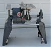
Maybe I should have read before I acted. But that would not have changed anything, really. I am one of those that has to do it myself no matter what.
I had the extension tables off, laying upside down on my workbench with an extension tube tieing them together. In this position, their four legs stick straight up in the air. A quick glance at them very quickly reveals that those legs travel in different planes.
I began a tear down to get to the root cause of my observations. These are not problems because they do no adversely effect functionality. This is just something that I must understand - and I will.
I'm at a new starting point. Guess I better take time to read ed's discertation.
- Attachments
-
- P1090025.JPG (151.72 KiB) Viewed 21133 times
-
- P1090026.JPG (159.02 KiB) Viewed 21124 times
-
- P1090027.JPG (152.18 KiB) Viewed 21123 times
"Making Sawdust Safely"
Dusty
Sent from my Dell XPS using Firefox.
Dusty
Sent from my Dell XPS using Firefox.

"...perhaps I'm a dreamer here, but having worked with the Shopsmith for over 20 years I still can not see any reason why the machine can not be brought into such alignment to permit the swapping of the Aux table from one side to the other and remain aligned."
No, Ed, you're not a dreamer. It is possible and it's a whole lot simpler than any of us have guessed here, all our long and learned treatises on the subject not withstanding. This afternoon, Jim McCann showed me a simple procedure for aligning the auxiliary table that results in an aux table that can be used on both sides of the machine. I came back back to the Academy, tried it on three different machines, and it worked as advertised.
There is a stack-up of tolerances, as Ed (Reible) pointed out, but we maintain sufficient precision in our manufacturing procedures that this should not be a problem. And the Mark V design includes the ability to adjust the frame alignment to compensate for small differences. Furthermore, the frame is rigid enough to hold it's alignment -- or this particular alignment -- even on uneven floors. After aligning the auxiliary tables on the three machines I mentioned, I propped up the various corners on scraps of wood to simulate wildy uneven floors and tables remained aligned.
The procedure is short and simple enough that I can show it to you on a Sawdust Session, so I've scheduled one on February 9. In the meantime, here are the bare bones:
1. Make sure your table is properly aligned to the saw blade. When the miter slots are perpendicular to the axis of rotation, the main table rails will be parallel to the way tubes.
2. Make sure the rails on both the main table and the auxiliary table are set to the proper height, using the aluminum gauge we supplied with the machine.
3. Make sure the main table surface is square to the saw blade.
Note: While all of these alignments are critical, none of them need be so precise that they cannot be accomplished with ordinary measuring equipment. The closer they are, the better this will work. But on the three machines I worked on, the miter slots were between .002" and .005" of parallel to the saw blade -- good alignment, but not quite up to military specs. This did not seem to adversely affect the results.
4. Place the auxiliary table in the base (right side) and loosen all the nuts that hold the table to the dogbone. Slide the table all the way to the right so it contacts the auxilary table.
5. Slide the connector tubes through the rails on both tables and tighten the locking knobs. Both tables should be at the same height if the rails (see #2) are set properly.
6. Adjust the nuts with your fingers so both the top and bottom nuts just touch the dogbone, then tighten them. Loosen the locking knobs. The connector tubes should slide back and forth through the rails in both tables easily.
7. Move the auxiliary table to the headrest (left side) and slide the table as close as possible. Adjust both tables to the same height and slide the connector tubes through the rails of the main table and into the rails of the auxilary table.
8. If the tubes bind or will not align with the auxiliary table rails, raise or lower the allen set screw in the headrest (under the way tube tie bar, toward the rear) until they do.
That's it, folks. Worked for me three times out of three. If it doesn't work for you, see me on February 9 and we'll talk.
With all good wishes,
Nick Engler
http://www.workshopcompanion.com
http://www.workshopcompanion.com
Today I "re-aligned the extension table on the right side of the unit as I have been captivated by this thread and have wondered about the concerns as I have not seen or envisioned a problem here and wanted to understand the issue.
Later on today, I moved the extension table to the left side. The alignment of the table seemed good without laying a straight edge. Then had to do a fixing job by drilling a few holes. When laying the tubes down I noticed the adjustment screw, in the headrest, and wondered why I have never adjusted it. Also noticed the circular indentation the screw has made in the way tube tie bar.
Just think of it! This little screw is the answer to the "issue of discussion" in these 18 (now 19) posts!:D Who'd of thunk!
Octogenarian's have an earned right to be a curmudgeon.
Chuck in Lancaster, CA
Chuck in Lancaster, CA
Well done Nick!
From my previous posting:
"3) Confusion as to what we should be expecting from our shopsmiths."
What I want is for an extension table that is adjusted on the right side be fully operational if moved to the left side. At this point we are still one step away proving that can be done. Other my expect the alignment of tubes to be enough but I'm not clear on what that actual proves or provides.
I've gotten as far as you (Nick) have discribed... maybe not quite as well as you have described but very close to that. As I mentioned in my posts here and before the problem is when you go to ripping operations. (I'll quote myself so you don't have to read through that again). "...it would work fine for supporting but not for mounting the rip fence on."
So the one thing left to do is ripping operations with the extension table mounted at each end by using the rip fence mounted in both positions. (Of course no tweeking/bumping or playing with the alignment of the fence is allowed unless mentioned in the instructions).
To do that I have done the following sort of operation. To check this I feel you need to do a nice wide rip cut with the rip fence on the right side using the extension table mounted there followed by a nice wide cut with the same table mounted on the right. (The idea is to have the blade and rip fence far from each other (as much as you can)). The length of cut needs to be say 24" long and no wider then can be done to a 4 foot wide piece.
I know the rip fence on the right will give you a nice rip however how close are you when you mount it on the other side? I had to devise a safe way of doing this test and managed to find out the operation wasn't quite to my likeing. It was clear in my testing that the rip fence and blade were not well suited on the left side mounting.
If you have the time Nick can you give your setup a check... something like I described that will prove the alignment between the rip fence to blade??? It will only take two cuts.....
Ed
{Knight of the Shopsmith} [Hero's don't wear capes, they wear dog tags]