Page 1 of 3
Mark VII Headstock Reassembly
Posted: Fri Jan 25, 2013 4:56 pm
by JPG
Starting with the belt cover.
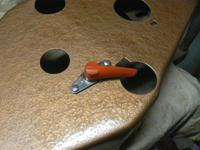
The Mark VII has some parts not included with a Mark 5/V. It has a way tube gear rack disconnect control. Normally the headstock cannot be moved except by cranking the positioning lever. The disconnect allows free wheeling so to speak(moving the headstock by pushing manually).
Two 'tinnerman' type clips provide captive 'nuts' for mounting the control bracket. Notice the 'extra' square cutout in the front way tube hole. That provides clearance for the gear rack mounted to the back of the 'front' way tube.
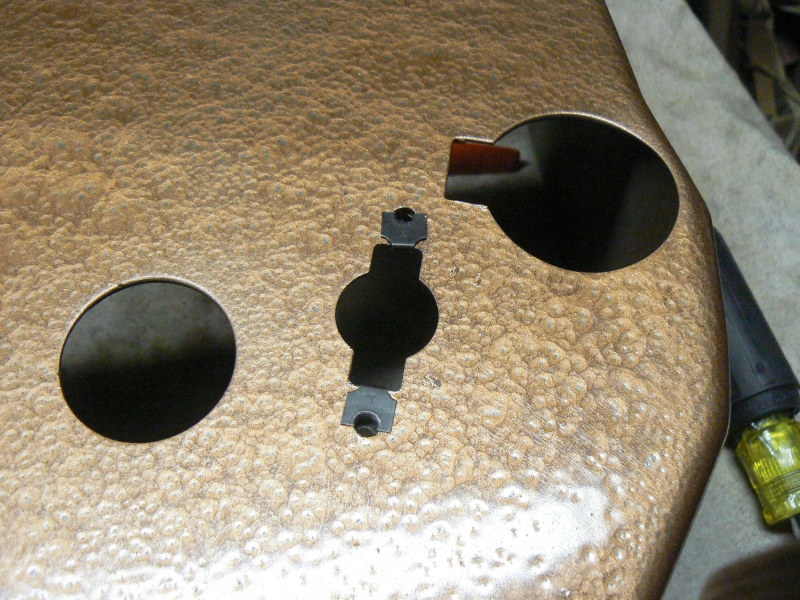
- belt cover1.jpg (472.03 KiB) Viewed 6779 times
The bracket is not flat so it must be positioned correctly to match the slope of the belt cover.
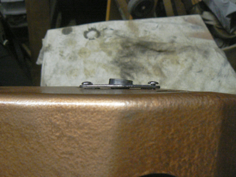
- belt cover2.jpg (378.94 KiB) Viewed 6767 times
The control shaft is inserted into the bracket bore from the inside.
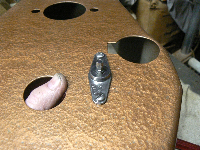
- belt cover3.jpg (471.98 KiB) Viewed 6783 times
This shows the cam end of the control shaft. It moves a plate that removes pins from the headstock positioning drive gear thus uncoupling the pinion gear that rides on the way tube gear rack . We shall see that stuff later.
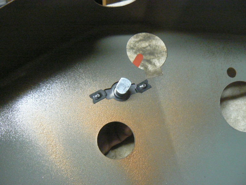
- belt cover4.jpg (428 KiB) Viewed 6780 times
The knob is all that holds the shaft in place. The knob set screw goes on a flat on the shaft.
The knob was slightly cracked, so I applied some CA and hope enough seeps in to keep it in one piece. The knob has a brass insert so that will help.
- belt cover5.jpg (434.44 KiB) Viewed 6776 times
This thread is linked go from
https://forum.shopsmith.com/viewtopic.php?t=11984
Posted: Fri Jan 25, 2013 5:47 pm
by JPG
Finally dere is de hole plug. The Mark VII did not have a vent plate when I acquired it. It will have something eventually.
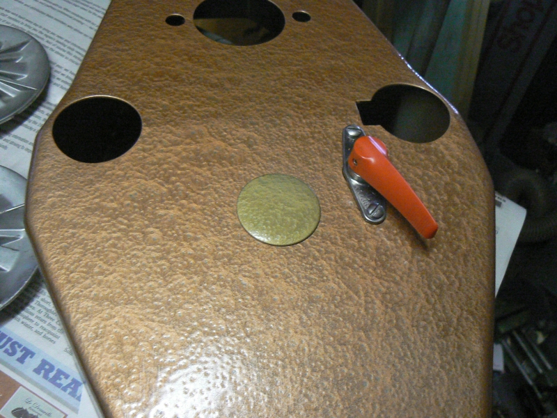
- belt cover6.jpg (441.35 KiB) Viewed 6750 times
Mark VII main shaft reassembly
Posted: Wed Feb 27, 2013 12:53 pm
by JPG
Now for the headstock casting reassembling.
Starting with the main shaft, the inner bearing retaining clip is started into its groove.
[ATTACH]20365[/ATTACH]
Then worked around until fully seated in the groove.
[ATTACH]20366[/ATTACH]
The shaft/bearing assembly is inserted through the rear bore, through the poly-v belt and into the front bore.
The Idler Shaft was installed next, but inadvertently got skipped over. It appears beginning with post #18.
[ATTACH]20367[/ATTACH]
Notice the front bearing protrudes from the front bore when fully seated.
[ATTACH]20368[/ATTACH]
Finally the rear bearing retaining ring is installed into it's groove.
[ATTACH]20369[/ATTACH]
I neglected to mention a couple of things when I first posted this.
The poly-v belt is wider than the Mark 5/V belt. It has 13 ribs and covers the entire face of the pulleys.
The idler sheave is not held in position by a clip, but rather is free to slide along the shaft.
This makes it self aligning. NO! It bears against the bearing positioning c-clip.
Another thing I neglected to do was document the reassembly of the idler shaft. It is however quite straight forward. I apologize for that omission.

I find it interesting that the Mark 5/V have always had a 13 rib pulley on the main shaft. Only the idler pulley is smaller(9 ribs).
Mark VII quill feed reassembly
Posted: Wed Feb 27, 2013 1:08 pm
by JPG
The Mark VII quill feed assembly is essentially the same as a Mark 5/V.
[ATTACH]20370[/ATTACH]
The spherical washer is installed with the concave side towards the casting ear(to the right in pix).
[ATTACH]20371[/ATTACH]
The sleeve goes over the woodruf key. This one is damaged, but I think it will work ok.
[ATTACH]20372[/ATTACH]
The spring washer and lock wing nut are last on the 'lock' side
[ATTACH]20373[/ATTACH]
Posted: Wed Feb 27, 2013 1:20 pm
by JPG
The return spring housing is positioned with the index aligned as originally.
[ATTACH]20374[/ATTACH]
There is no washer between the retaining clip and the inner serrated washer as is typical for this vintage Mark 5's. The serrated sides of the washers face the lock index dial.
The spring housing is secured by the set screw(not shown in pix - only the hole!)
[ATTACH]20375[/ATTACH]
Finally the wing nut is attached.
[ATTACH]20376[/ATTACH]
The handle(not in pix) mounts the same as the Mark 5/V/7 on either end of the quill feed shaft.
Mark VII Quill/headstock reassembly
Posted: Wed Feb 27, 2013 1:35 pm
by JPG
I prefer a 'dowel' and mallet to install the spline shaft coupler.
[ATTACH]20377[/ATTACH]
I had the wishful thought that I would install a new two bearing quill rather than the 'original'. It did not fit!:mad: It was too long and would not retract fully.
[ATTACH]20378[/ATTACH]
I am suspicious of the 'original' quill. It has a blox shaft which is not typical for this vintage. It also appears to have been cut off. May or may not have been by a PO.
I simply do not know what the original Mark VII was.
My suspicions have been confirmed. A subsequent arrival of an actual Mark VII quill has a shorter splined shaft. I have since replaced the cut off one with the 'real' one.
[ATTACH]20379[/ATTACH]
So I will have to back up and refurb the quill that came with it when I acquired it.
I will add that quill to this post/thread later.
'Later' is post #12 this thread.
Mark VII counter shaft/headstock reassembly
Posted: Wed Feb 27, 2013 1:54 pm
by JPG
Moving on to unique Mark VII hardware. The 'counter shaft' allows mounting the headstock positioning spur gear, clutch and bevel gear. The shaft extends downward from the bottom of the headstock casting. It is probably driven into the casting and wedged there by small splines. In any event, I made no attempt to remove it.
[ATTACH]20380[/ATTACH]
The shaft has three grooves that are for retaining rings.
[ATTACH]20381[/ATTACH]
A clip is installed in the first groove.
[ATTACH]20382[/ATTACH]
The spur gear goes on next. Notice the notches are facing out.
[ATTACH]20383[/ATTACH]
Next the bevel gear and a second clip. As we shall see later, the notches in the spur gear can align with the holes in the bevel gear.
[ATTACH]20384[/ATTACH]
Posted: Wed Feb 27, 2013 2:15 pm
by JPG
Next the clutch and spring. The clutch pins extend through the holes in the bevel gear and into the notches in the spur gear.
[ATTACH]20385[/ATTACH]
A washer and a third clip finish it off.
[ATTACH]20386[/ATTACH]
The clutch is moved by the lever mounted on the belt cover. More about that later.
Mark VII lock shaft headstock reassembly
Posted: Wed Feb 27, 2013 5:37 pm
by JPG
I call this a lock shaft because it functions as the headstock lock. It also provides headstock positioning.
[ATTACH]20392[/ATTACH]
Crank/lever is reattached to shaft by by a tension pin. The pin is pressed flush to both ends.
[ATTACH]20393[/ATTACH]
Crank 'cover' is secured by three screws. The notch provides later access to the motor pan retaining screws.
[ATTACH]20394[/ATTACH]
The shaft is inserted through the crank 'hub' and a spacer and the front wedge are slipped onto the shaft. The wedge 'flat' faces the rear. The wedges have straight bores(Not threaded).
[ATTACH]20395[/ATTACH]
The spacer in inserted into the crank hub.
[ATTACH]20396[/ATTACH]
Posted: Wed Feb 27, 2013 5:48 pm
by JPG
The worm gear is slipped onto the shaft. A small woodruff key goes into a keyway in the bore of the gear. The worm gear meshes with the bevel gear on the counter shaft.
[attach]20397[/attach]
Next on the shaft is a long spacer.
[attach]20398[/attach]
A bracket goes over the shaft between the spacer and the gear and the front wedge.
[attach]20399[/attach]
Two short screws secure the bracket. These were really torqued down when disassembled.
[attach]20400[/attach]
Next are the larger flat washer and a spring.
[attach]20401[/attach]