Using a Shop Smith Mark V on a Chris Craft Roamer refit
Moderators: HopefulSSer, admin
-
thunderbirdbat
- Platinum Member
- Posts: 788
- Joined: Sat Aug 08, 2015 11:23 am
- Location: Marion, Iowa
Re: Using a Shop Smith Mark V on a Chris Craft Roamer refit
Lets see if I can translate simple electronic theory to basic piping theory to give you an idea as to how it works. It is not perfect but gives a general idea of how it works. A resistor is a form of reducer, a diode is similar to a check valve, a transistor an enlarger and a capacitor is like a small holding tank that once it fills, will dump all at once. the wires are basically like the pipes. Heat is the by-product of each change to the energy flow. The warmer it is the harder it is to dissipate the heat, which can cause problems with the equipment operation. This is the reason most electronic spaces are kept at very cool temperatures. It is not really what happens but as an electronics tech that was forced to learn how piping systems work for quality assurance, it is sufficient to give an idea of what is going on to someone familiar with piping. IC chips are just smaller compact versions of resistors, diodes, transistors and the wiring between them. For physical indications, resistors normally break when they go bad, capacitors may leak or split, diodes and transistors do not give an indication.
Brenda
1998 510 upgraded to a 520, upgraded to power pro with double tilt and lift assist.
1998 bandsaw
2016 beltsander
jointer
overarm pin router
1998 510 upgraded to a 520, upgraded to power pro with double tilt and lift assist.
1998 bandsaw
2016 beltsander
jointer
overarm pin router
Re: Using a Shop Smith Mark V on a Chris Craft Roamer refit
Thanks for that explanation.
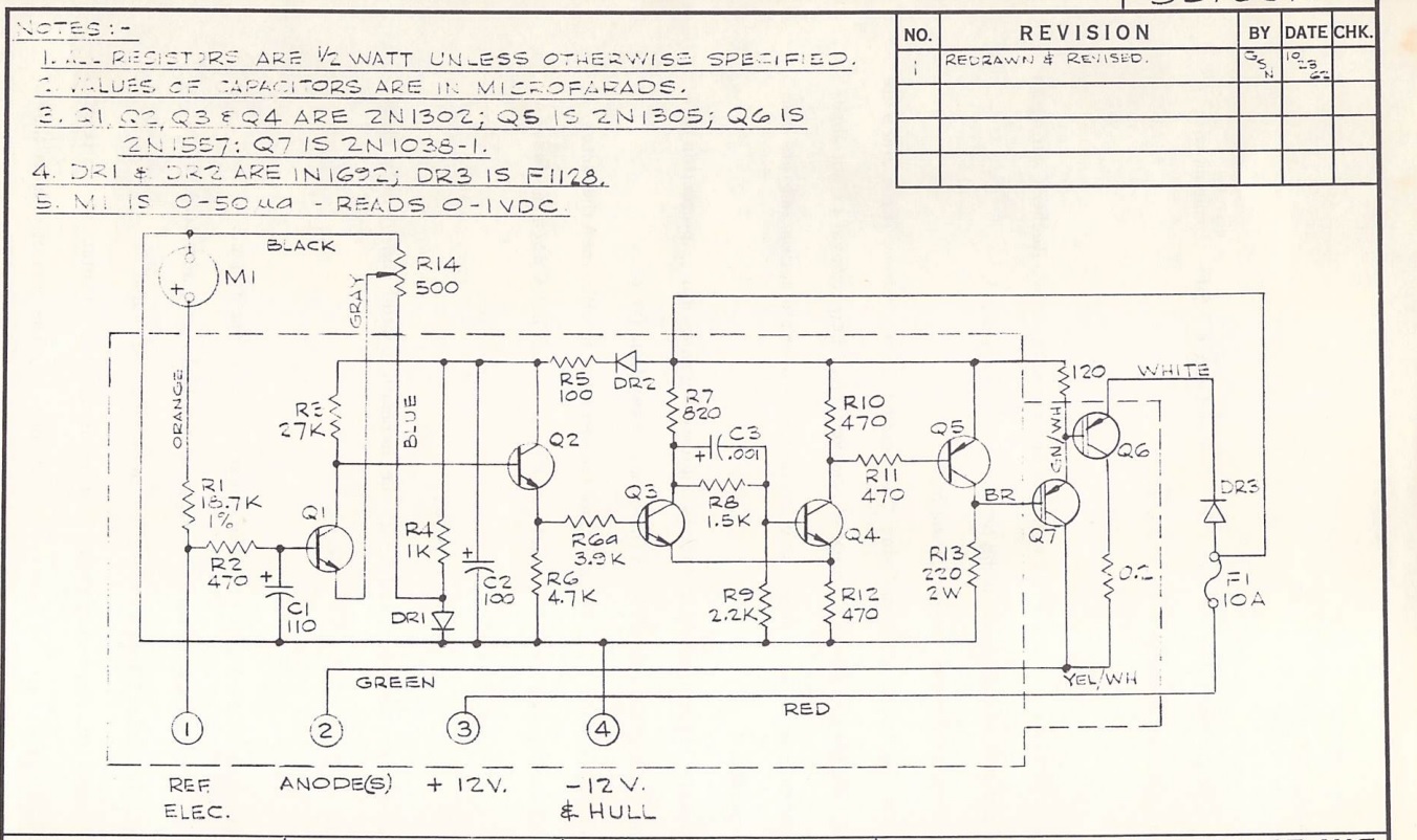
The explanation of how the CAPAC controller works (p. 24 of the manual linked from the blog) indicates "When the voltage at the base of Q3 falls below 4volts, Q4 starts to conduct. This increases the voltage on R12 and causes Q3 to cut off. While Q4 is conducting, current can pass from the base of Q5. This causes the voltage across R13 to be nearly equal to the battery voltage appearing at terminal 3. Therefore, no current can pass from the base of Q6 and Q7, and no anode current is available."
That appears to be the state of mine. I posted a picture of the circuit board schematic with voltage readings taken at various places. R13 does, indeed, have 13.31v across it. And I saw 0.129v at the base of Q3.
The manual also states "the difference between the desired hull potential voltage set on R14 and the reference cell voltage appearing at terminal 1is amplified by Q1 and Q2. This voltage appears across R6 and is connected to the base of Q3. If this voltage exceeds approximately 5 volts, Q3 will conduct and because of the coupling to Q4 will cause Q4 to turn off (non-conducting)."
R14 is the set point adjustment potentiometer on the face plate. Cranking it all the way clockwise, and all the way counterclockwise has no apparent effect. The needle doesn't budge.
Re: Using a Shop Smith Mark V on a Chris Craft Roamer refit
If I understand your annotation, you measured 0.000 VDC on the Blue wire going to the potentiometer (R14). The schematic shows the Black wire going from R14 to the common ground, therefore also 0 VDC. The Theory of Ops says that 'Rectifier (diode) DR1 is used to generate a regulated voltage of 0.7 VDC across the potentiometer R14.' You should have approximately 0.7 VDC at the junction of R4 and DR1 and also at the Blue wire going to the pot. Worth double checking. 0 VDC at both locations would tend to indicate DR1 is shorted or R14 open (less likely). To check the diode by itself, you need to lift at least one leg from the board to isolate it from everything else. Does you meter, evidently digital, have a diode test function?
- David
Re: Using a Shop Smith Mark V on a Chris Craft Roamer refit
Thanks David! It looks like you're reading my annotations correctly.
I've been giving the greasy eyeball to that blue wire for two days, since I suspected it should be seeing .7vdc instead of 0.000. R4 (1kohm) is seeing +11.24vdc on one leg and connects to the DR1 diode on the other (along with the blue wire), while the opposite leg of DR1 connects to -12vdc or battery/hull ground. The blue wire voltage (0.000v) is the same at the junction of R4 and DR1.
I'm curious--if DR1 is shorted, shouldn't the +11.24v still pass through R4 (assuming it's good) and show up on the blue wire, minus whatever portion the resistor blocked?
I've got a Fluke 15b and it's got a never-before-used diode function.
The schematic NOTES box also indicates that DR1 is "IN1692." Searching the internet, I see lots of PDFs from the 1960s that specify that diode, including one from NASA. But I'm not seeing any sellers of that part number or a modern equivalent assuming it's obsolete. I'll focus on testing the diode first and, if it's bad, try to figure out a replacement later.
Thanks again for the help.
Q
-
thunderbirdbat
- Platinum Member
- Posts: 788
- Joined: Sat Aug 08, 2015 11:23 am
- Location: Marion, Iowa
Re: Using a Shop Smith Mark V on a Chris Craft Roamer refit
Could the notes actually say 1N1692 instead of IN1692? 1N1692 is a recognized rectifier diode part number.
Brenda
1998 510 upgraded to a 520, upgraded to power pro with double tilt and lift assist.
1998 bandsaw
2016 beltsander
jointer
overarm pin router
1998 510 upgraded to a 520, upgraded to power pro with double tilt and lift assist.
1998 bandsaw
2016 beltsander
jointer
overarm pin router
Re: Using a Shop Smith Mark V on a Chris Craft Roamer refit
I wondered the exact same thing!
I went to a technical high school ages ago, and in drafting class we were taught that 1 and I are not written the same. But I can't tell the difference between the two on the schematic. Can you?
I went to a technical high school ages ago, and in drafting class we were taught that 1 and I are not written the same. But I can't tell the difference between the two on the schematic. Can you?
Re: Using a Shop Smith Mark V on a Chris Craft Roamer refit
The 1N prefix is/was commonly used for diodes where 2N is for transistors. I didn't catch that before. I don't recall the reasoning, and it might be old school now. This was extremely common in my time in the service, late 70's. Maybe it is a Mil-Spec number.(?) Because of that, I read all of these as 1N, and am reasonably certain that is correct. I agree regarding 1's and I's in the drawing, they should be clearly differentiated.
- David
Yes but in this case it would be 100%. Electrical current will still pass through R4 if the diode is shorted, but the ground via the presumed short will result in a 0V reading. So in this case the full 11.24V is being 'dropped' (converted to heat) by the resistor. If this was working correctly it would look similar to the R5 and DR2 combination you also noted, with voltage drops across both DR2 (also 0.7 V) and R5.
- David

Re: Using a Shop Smith Mark V on a Chris Craft Roamer refit
Well, all the 1/I numbers/letters look the same in the print. Clearly the word "is" on the print is a letter but all the electronic parts also have the same script for the number 1. i.e "Q5 IS 2NI305". That is thirteen oh five not the letter I 305.
Diodes are 1N not IN. similarly the number is 1692 not I692.
1N1692 are readily available.
Diodes are 1N not IN. similarly the number is 1692 not I692.
1N1692 are readily available.
John & Mary Burger
Eagle's Lair Woodshop
Hooper, UT
Eagle's Lair Woodshop
Hooper, UT
-
BuckeyeDennis

- Platinum Member
- Posts: 3697
- Joined: Tue Jul 24, 2012 10:03 pm
- Location: Central Ohio
Re: Using a Shop Smith Mark V on a Chris Craft Roamer refit
FWIW, the number preceding the "N" indicates the number of junctions that the device contains. Diodes have one junction, and bipolar transistors have two.
-
thunderbirdbat
- Platinum Member
- Posts: 788
- Joined: Sat Aug 08, 2015 11:23 am
- Location: Marion, Iowa
Re: Using a Shop Smith Mark V on a Chris Craft Roamer refit
Actually this is the way many of the schematics were written from the '40's,'50's and '60's that I have seen. I am not sure when the writing was changed to distinguish between an I and a 1 but all of the older schematics I worked with did not.
Brenda
1998 510 upgraded to a 520, upgraded to power pro with double tilt and lift assist.
1998 bandsaw
2016 beltsander
jointer
overarm pin router
1998 510 upgraded to a 520, upgraded to power pro with double tilt and lift assist.
1998 bandsaw
2016 beltsander
jointer
overarm pin router