Page 1 of 3
motor reversing switch
Posted: Thu May 07, 2015 12:39 am
by JPG
This thread is intended to answer a PM from 5speedsoffury(sp??) since I do not know how to attach to a PM.
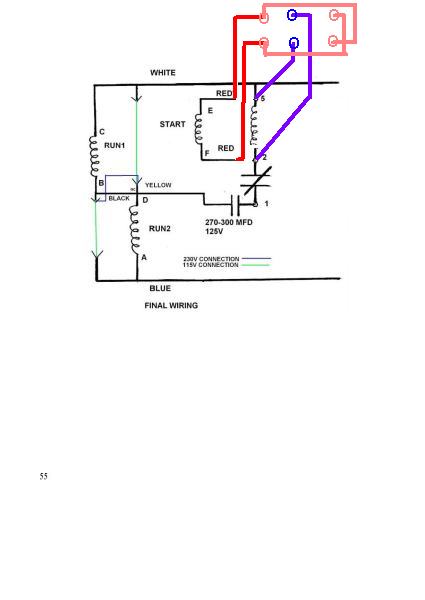
- burnt motor final rev sw.jpg (14.87 KiB) Viewed 3296 times
Re: motor reversing switch
Posted: Thu May 07, 2015 9:42 am
by 5speedsoffury

this should do! I am going to follow this schematic tonight. I'll try to post up a good picture of the finished wiring when I am done! Thanks JPG!
Re: motor reversing switch
Posted: Thu May 07, 2015 10:54 am
by dusty
In this diagram, do the two green wires represent connections that are to be made if 110vac is the source?
If yes, do those two green wires not then create a direct short from the white wire to the blue wire (i.e. shorting across the run windings)?
Re: motor reversing switch
Posted: Thu May 07, 2015 11:31 am
by JPG
dusty wrote:In this diagram, do the two green wires represent connections that are to be made if 110vac is the source?
If yes, do those two green wires not then create a direct short from the white wire to the blue wire (i.e. shorting across the run windings)?
The thin green and blue lines indicate different connections for the two different input voltages.
Only the two green connections are made for 115v. That places the two run windings in parallel.
For 230v operation, the green connections are NOT made, but the blue one
(from "B" to "D") is added so as to connect the two run windings in series.
There is NO connection of the crossing wires at "D" nor any of the red/blue wires added for the reversal switch.
Notice the 'arrow heads'. They represent male/female connectors that allow the optional 115v / 230v connections. Thus the thin green/blue lines are not wires, but indication of how those connectors are connected. All the connectors are shrouded which eliminates potential of open connectors shorting to external parts.
The drawing was the last page of a HTML that 5speedsoffury referenced in his PM to me(and Bill). The intent of this post was to show him how to connect a DPDT switch to control run direction. I did not find a way to attach a jpeg to a PM. Somehow, he managed to attach a html to his PM.
????????? How'd he do dat

Re: motor reversing switch
Posted: Thu May 07, 2015 12:10 pm
by dusty
Thank you. On my monitor it is hard to distinguish that the wire from d to b is blue. I was reading it as though it was a permanent connection.
Re: motor reversing switch
Posted: Sun May 10, 2015 1:37 pm
by 5speedsoffury
Thank you JPG! Wiring in the DPDT switch was successful!
Re: motor reversing switch
Posted: Sun May 10, 2015 2:06 pm
by 5speedsoffury
Pardon the crazy wiring mess
Re: motor reversing switch
Posted: Sun May 10, 2015 2:17 pm
by 5speedsoffury
I just had 2 tabs open copied the url I had open in one tab and pasted it into a message I had wrote to you and Bill Mayo. Posting pictures on here was frustrating though. I couldn't figure it out till I realized there was a file size limit of 2MB
JPG wrote:dusty wrote:In this diagram, do the two green wires represent connections that are to be made if 110vac is the source?
If yes, do those two green wires not then create a direct short from the white wire to the blue wire (i.e. shorting across the run windings)?
The thin green and blue lines indicate different connections for the two different input voltages.
Only the two green connections are made for 115v. That places the two run windings in parallel.
For 230v operation, the green connections are NOT made, but the blue one
(from "B" to "D") is added so as to connect the two run windings in series.
There is NO connection of the crossing wires at "D" nor any of the red/blue wires added for the reversal switch.
Notice the 'arrow heads'. They represent male/female connectors that allow the optional 115v / 230v connections. Thus the thin green/blue lines are not wires, but indication of how those connectors are connected. All the connectors are shrouded which eliminates potential of open connectors shorting to external parts.
The drawing was the last page of a HTML that 5speedsoffury referenced in his PM to me(and Bill). The intent of this post was to show him how to connect a DPDT switch to control run direction. I did not find a way to attach a jpeg to a PM. Somehow, he managed to attach a html to his PM.
????????? How'd he do dat
Re: motor reversing switch
Posted: Sun May 10, 2015 2:29 pm
by JPG
5speedsoffury wrote:Pardon the crazy wiring mess
Now for the hard part. Where to drill the 15/32" hole.
I like the front of the motor pan close to the near side(crowded inside though).
Re: motor reversing switch
Posted: Sun May 10, 2015 3:50 pm
by 5speedsoffury
That's the question I have asked myself from the start. The DPDT switch is easily disconnected from the motor so I was thinking about mounting it the on the aluminum cast housing. But I like your idea too. Does anybody else have any suggestions? Pictures are encouraged! My comprehending of written text seems to lack so visualizing is difficult