I find this problem when the quadrant roll pin wears the holes bigger in the legs of the speed control bracket causing the quadrant to tilt and is no longer centered on the control sheave bearing button. The legs also spread apart due to the mismatch between the quadrant teeth and the steel worm control gear. This causes the quadrant teeth to wear quickly as they are no longer centered on the steel worm control gear of the Speed Control Assy. If you are changing the speed quite often, then the teeth on the new quadrant will again wear more on one side than the other side slowly destroying the teeth and make changing speed quite hard or impossible again. Of course, I developed a solution for this problem a few years ago.
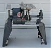
The quadrant roll pin wears the holes and with the legs spreading apart, it will cause the quadrant teeth to wear uneven. I have converted all my spare Speed Control Assemblies to a hex head bolt, star washers and lock nut. I used a center punch to close up the leg holes so the wear is now only between the bolt and quadrant, not the legs. I have been using these modified Speed Control Assemblies for several years with no new problems and the quadrant teeth look new each time I lubicate my headstocks. Picture 716 is before and 758 is with my fix. I have more pictures and a more lengthly explanation for anyone who would like it.
charlese wrote:I don't think the headstock housing would bend. I think it would break first since it is cast. My guess, (but it is a guess) the eccentric bushing that is used to adjust the poly V belt could somehow become cocked in the hole. Try removing the eccentric which will allow you to remove the entire idler shaft and control sheave. Inspect and replace worn or mis-shapen parts, or just re-install what you have. Inspection, while removed will show you how those parts function. Also you can see if there is rotational play between the parts.
I may be wrong about the bending thing. Bill Mayo would know!
Attachments
IMG_0758.JPG (49.21 KiB) Viewed 5728 times
IMG_0716.JPG (39.01 KiB) Viewed 5726 times
Bill Mayo bill.mayo@verizon.net
Shopsmith owner since 73. Sell, repair and rebuild Shopsmith, Total Shop & Wood Master headstocks, SPTs, attachments, accessories and parts. US Navy 1955-1975 (FTCS/E-8)
billmayo wrote:I find this problem when the quadrant roll pin wears the holes bigger in the legs of the speed control bracket causing the quadrant to tilt and is no longer centered on the control sheave bearing button. The legs also spread apart due to the mismatch between the quadrant teeth and the steel worm control gear. This causes the quadrant teeth to wear quickly as they are no longer centered on the steel worm control gear of the Speed Control Assy. If you are changing the speed quite often, then the teeth on the new quadrant will again wear more on one side than the other side slowly destroying the teeth and make changing speed quite hard or impossible again. Of course, I developed a solution for this problem a few years ago.
The quadrant roll pin wears the holes and with the legs spreading apart, it will cause the quadrant teeth to wear uneven. I have converted all my spare Speed Control Assemblies to a hex head bolt, star washers and lock nut. I used a center punch to close up the leg holes so the wear is now only between the bolt and quadrant, not the legs. I have been using these modified Speed Control Assemblies for several years with no new problems and the quadrant teeth look new each time I lubicate my headstocks. Picture 716 is before and 758 is with my fix. I have more pictures and a more lengthly explanation for anyone who would like it.
Bill,
Please post the info on bolt size to use and any little ins-and-outs you use to get the guadrant back in shape. You really are the go to guy.
thanks.........ldh
I know this thread is from 2008, but I was hoping someone might still be able to help.
I bought a 1959 mark v "greenie" from a good friend who moved away. After sitting in my garage a good year I'm now finally able to start digging into this amazing thing.
Long story short, I have the headstock disassembled because it was seizing up. From what I've been able to diagnose, the snap-on rectangular retaining loop broke off.
I do see I can replace the entire piece for about $60, but the thing is, I'm really trying to not spend much at this point; I could get an entire used one for $300, so it seems unreasonable to spend $60 on a single part. That said, I was unable to locate the single part (item 112 on the exploded diagram); it looks like it was only part of the whole Control Sheave. I just need the clip.
Does anyone know if you can purchase this separately? If not... any suggestions for rebuilding one? Or am I done at this point and might as well scrap it? Thanks in advance.
YOU MAY ALSO NEED THE ROLL PIN (GET FROM LOCAL HARDWARE STORE!)
╔═══╗
╟JPG ╢
╚═══╝
Goldie(Bought New SN 377425)/4" jointer/6" beltsander/12" planer/stripsander/bandsaw/powerstation /Scroll saw/Jig saw /Craftsman 10" ras/Craftsman 6" thicknessplaner/ Dayton10"tablesaw(restoredfromneighborstrashpile)/ Mark VII restoration in 'progress'/ 10E[/size](SN E3779) restoration in progress, a 510 on the back burner and a growing pile of items to be eventually returned to useful life. - aka Red Grange
These parts often fail when the 'button bearing' seizes, even partially. IIWM I'd carefully check that bearing before feeding it a set of the connecting parts. The basic design is that the button at the center does not spin while everything else does. (See pics earlier in this thread.) If the bearing is bad and the sheave is otherwise good, there is an aftermarket parts source on ebay for a new bearing with the clip, roll pin, button, etc. Shopsmith does not sell the bearing separately from the sheave.
You may find your pin and clip in the motor pan, if yes you can sometimes straighten the clip.
Goldie(Bought New SN 377425)/4" jointer/6" beltsander/12" planer/stripsander/bandsaw/powerstation /Scroll saw/Jig saw /Craftsman 10" ras/Craftsman 6" thicknessplaner/ Dayton10"tablesaw(restoredfromneighborstrashpile)/ Mark VII restoration in 'progress'/ 10E[/size](SN E3779) restoration in progress, a 510 on the back burner and a growing pile of items to be eventually returned to useful life. - aka Red Grange