bigmoe wrote:Jim, I am wondering what roll pin you are talking about in the control sheave I have a 1955 Mark V and the only hole in the control sheave is the one for oiling the shaft. Somewhere I read that the Greenies do not have that hole in the control sheave, and if it doesn't it is recommended to drill a oil hole. The key way on the shaft is what keeps the sheaves lined up.
Hi bigmoe,
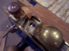
The picture shows quite clearly that the loop on the end of the sheave fits into a roll pin that goes through the shaft on the end of the sheave. If you do not have that hole in the shaft, how does your loop connect to your sheave?
Tim
Buying US made products will help keep YOUR job or retirement funds safer.
Sorry about that I must of had my mind in neutral. After I went out and looked at mine laying on my workbench I seen the roll pin. I guess I was thinking the end of the control sheave was wider than it is.
Anyway I was wrong.
1955 Mark V ShopSmith greenie New to me Magna Band saw, Magna Jointer, Magna Jigsaw (Restoration in progress) Barracuda Wood Lathe Key Chuck System, Woodmaster Multi-tool (ShopSmith Clone) When all else fails fallow directions.
Yes, I find the Greenies I rebuild do not have a oil hole in the control or floating sheaves. I drill a 5/32" hole on the keyway 3/16" from the raised collar on both sheaves. Since I cannot get to the control sheave to oil it, I drill a 3" hole (metal hole saw) centered between the holes that hold the LOGO cover. I have a jig I made for centering the hole. I then use a 3/4" wide flat aluminum bracket the length of the LOGO diameter with a hole drilled at the top and bottom of the LOGO cover and matching holes in the bracket. I use 2 #8 sheet metal screws to hold the logo cover to the bracket. This allows me to oil the control sheave and blow sawdust from the headstock during maintenance checkups.
bigmoe wrote:Jim, I am wondering what roll pin you are talking about in the control sheave I have a 1955 Mark V and the only hole in the control sheave is the one for oiling the shaft. Somewhere I read that the Greenies do not have that hole in the control sheave, and if it doesn't it is recommended to drill a oil hole. The key way on the shaft is what keeps the sheaves lined up.
Bill Mayo bill.mayo@verizon.net
Shopsmith owner since 73. Sell, repair and rebuild Shopsmith, Total Shop & Wood Master headstocks, SPTs, attachments, accessories and parts. US Navy 1955-1975 (FTCS/E-8)
I have another related question. The speed control arm does not line up straight with the center of the control sheave.
Is there an adjustment that can be made or does this indicate that something is bent which has thrown them out of alignment?
I have installed a new speed control as the previous one was obviously bent badly.
The history of this machine is that I just bought it a few months ago and have never used it personally. I am hoping to get the basic mechanicals operational, so I can fine tune the machine and eventually get some good use out of it.
If you have a new speed control, about the only other thing having a small influence on the line-up of these parts would be the belt-tension adjust, which moves the idler pulleys up and down slightly. I don't know the spec's on the overlap between speed-control and control sheeve, but perhaps they can't be guaranteed to be dead-on every time?
jbuis wrote:I have another related question. The speed control arm does not line up straight with the center of the control sheave.
Is there an adjustment that can be made or does this indicate that something is bent which has thrown them out of alignment?
Thanks,
Jim
I assume by 'speed control arm' you mean the quadrant. If so, it should line up directly in front (back) of the control sheave shaft. See the following: third photo in post #6 and first photo in post #8.
If it doesn't line up - there is likely something awry with the "Idler shaft assembly" or the eccentric bushing. I suggest asking Shopsmith to send you a copy of the instructions for replacing the Idler Shaft Assembly. When you get them, they will give you enough knowledge to disassemble your unit and take a look.
I am assuming you have checked the control sheave along with the key and keyway.
Octogenarian's have an earned right to be a curmudgeon.
Chuck in Lancaster, CA
charlese wrote:I assume by 'speed control arm' you mean the quadrant. If so, it should line up directly in front (back) of the control sheave shaft. See the following: third photo in post #6 and first photo in post #8.
If it doesn't line up - there is likely something awry with the "Idler shaft assembly" or the eccentric bushing. I suggest asking Shopsmith to send you a copy of the instructions for replacing the Idler Shaft Assembly. When you get them, they will give you enough knowledge to disassemble your unit and take a look.
I am assuming you have checked the control sheave along with the key and keyway.
Yes, I was trying to describe the quadrant. It does not line up as in the photos. I have run my Shopsmith and there is no sign of bent shafts. I am afraid that the headstock housing may have been bent when the speed control was previously damaged.
I don't think the headstock housing would bend. I think it would break first since it is cast. My guess, (but it is a guess) the eccentric bushing that is used to adjust the poly V belt could somehow become cocked in the hole. Try removing the eccentric which will allow you to remove the entire idler shaft and control sheave. Inspect and replace worn or mis-shapen parts, or just re-install what you have. Inspection, while removed will show you how those parts function. Also you can see if there is rotational play between the parts.
I may be wrong about the bending thing. Bill Mayo would know!
Octogenarian's have an earned right to be a curmudgeon.
Chuck in Lancaster, CA
I find this problem when the quadrant roll pin wears the holes bigger in the legs of the speed control bracket causing the quadrant to tilt and is no longer centered on the control sheave bearing button. This causes the quadrant teeth to wear quickly as they are no longer centered on the steel worm control gear of the Speed Control Assy. If you are changing the speed quite often, then the teeth on the new quadrant will again wear more on one side than the other side slowly destroying the teeth and make changing speed quite hard or impossible again. Of course, I developed a solution for this problem a few years ago.
Since the quadrant roll pin wears the holes causing the quadrant teeth to wear uneven, it may jam or make changing the speed quite hard. I have converted all my spare Speed Control Assemblies to a hex head bolt, star washers and lock nut. I used a center punch to close up the leg holes so the wear is now only between the bolt and quadrant, not the legs. I have been using these modified Speed Control Assemblies for several years with no new problems and the quadrant teeth look new each time I lubicate my headstocks. I have more pictures and a more lengthly explanation for anyone who would like it.
charlese wrote:I don't think the headstock housing would bend. I think it would break first since it is cast. My guess, (but it is a guess) the eccentric bushing that is used to adjust the poly V belt could somehow become cocked in the hole. Try removing the eccentric which will allow you to remove the entire idler shaft and control sheave. Inspect and replace worn or mis-shapen parts, or just re-install what you have. Inspection, while removed will show you how those parts function. Also you can see if there is rotational play between the parts.
I may be wrong about the bending thing. Bill Mayo would know!
Bill Mayo bill.mayo@verizon.net
Shopsmith owner since 73. Sell, repair and rebuild Shopsmith, Total Shop & Wood Master headstocks, SPTs, attachments, accessories and parts. US Navy 1955-1975 (FTCS/E-8)