Since there is a potential for physical harm and even death take what I'm telling you and read with caution. As always if you don't feel you know what you are doing or are scared it is best you stay away from this or seek the help of a qualified person to help you.
This is for educational purposes only and should not be construed as instructions for the making or use of this system. I will try and explain what I have done and why I did what I did. Again this is only my opinion and I am no expert on the subject.
I went to ebay and found a microwave transformer out of a physically damaged microwave meaning the transformer should be in like new condition. I have no proof of this but the word of the seller.
I went to amazon for some high voltage wire that is normally used for test leads on meters. For this I was looking for something that would/could provide 10KV isolation. This is the wire:
https://www.amazon.com/gp/product/B000L ... UTF8&psc=1
Bad news is you have to purchase a lot of wire that is not going to get used for this project. It is 18 GA FYI. The wires could be next to each other and still not have any problem as the potential of this unit is far below the isolation value of the wires. If you are using some other transformer this might not be the case so it doesn't hurt to keep the wires separated. Also keep in mind the outside of the transformer is at the full output voltage in reference to the output wire.
The transformer I got had primary input terminals, some wires for some other sub voltage and a single high voltage output. The physical frame of the transformer provides the other side of the high voltage output.
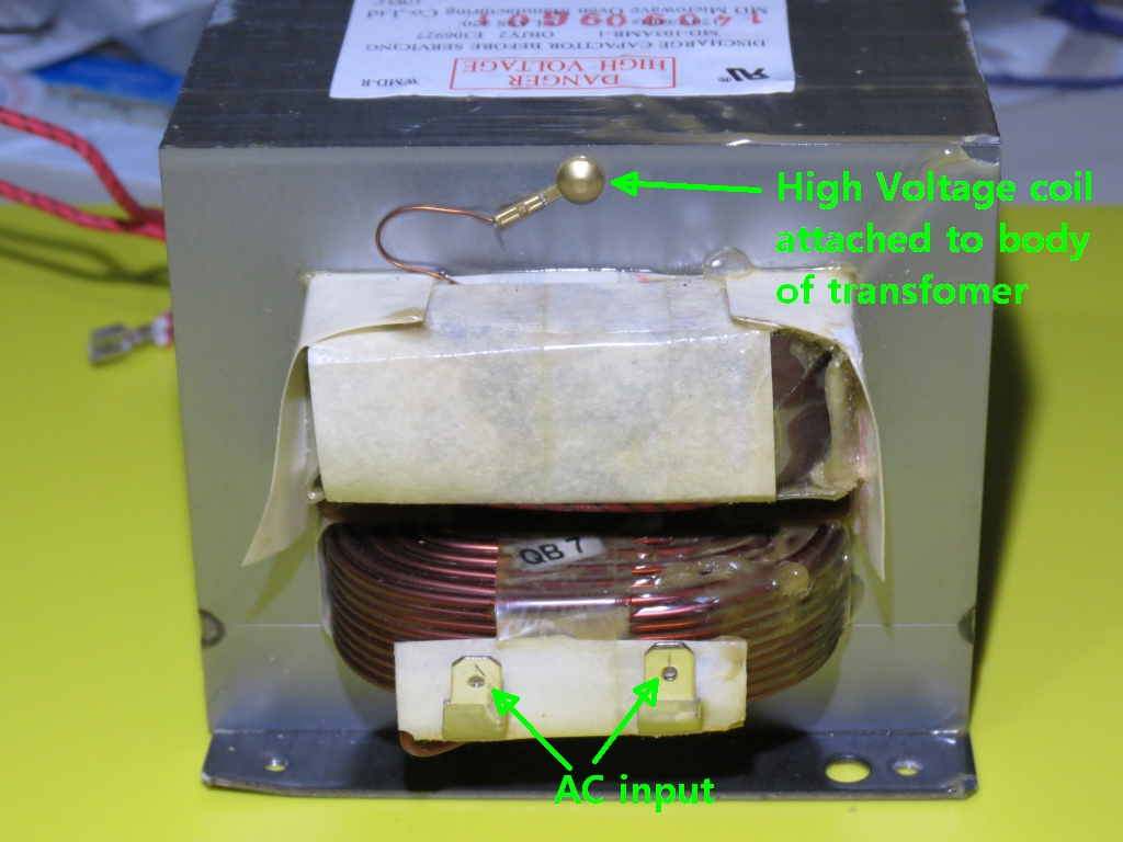
- IMG_2636scm.jpg (490.09 KiB) Viewed 11949 times
The input on another unit may or may not look like this. In general the large gauge wire of the primary is a give away.
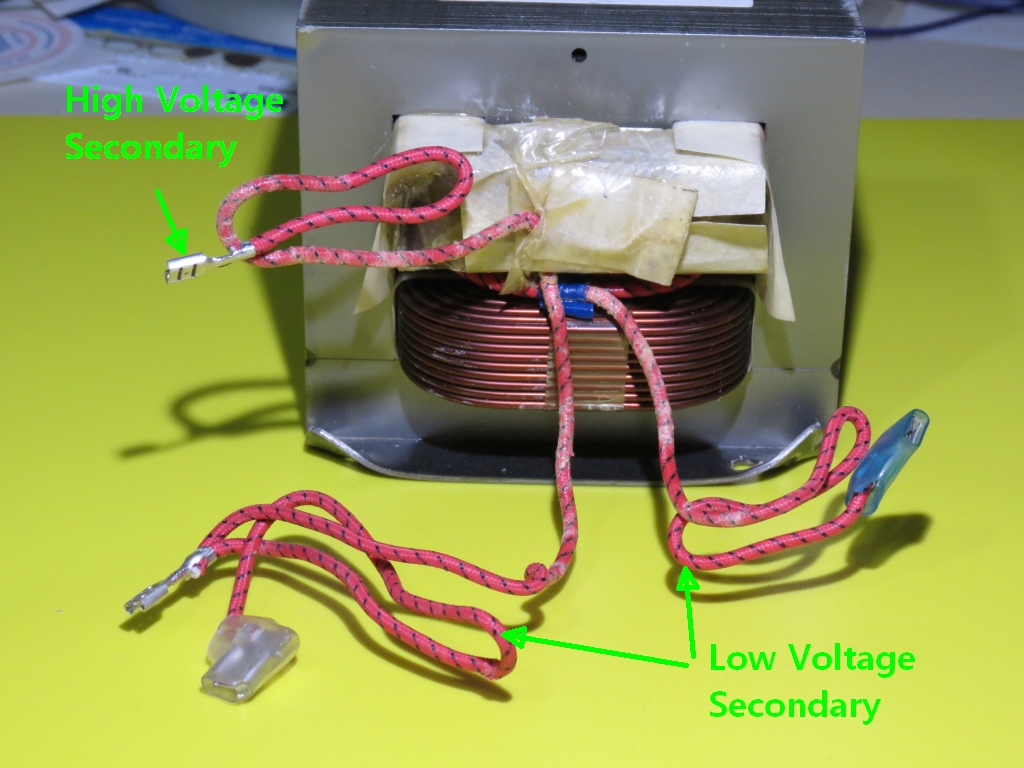
- IMG_2637scm.jpg (502.43 KiB) Viewed 11949 times
The unused wires should be cut short and taped so nothing can contact them. The output will be a single wire or at least it was in this case.
I used a ohm meter to check the input for conductivity and also to make sure that there were no connections to any of the other wires. Like wise I did the other wires, the lower voltage outputs will show conductivity to each other and nothing else. The high voltage will show conductivity to the metal frame and nothing else. You should make sure you know what is what before hooking this up to power.
I also wanted to know a bit more about the transformer I purchased but unable to find that part number for information. One thing I hoped to find is the output voltage. One thing you can do so long as the transformer is not load is to apply line voltage to the output and then measure the input voltage. This ratio of voltage is then used to give you a good idea of the output voltage because of the ratio it provides. From this I gather the voltage to be about 2300 volts. This was lower then I expected.
Next I started to look at a way to limit the current that one of these can deliver. In a lot of cases the people doing these simply hooked them up and burned away. Some got some pretty big flames........
What I did was to added an electrical box with an outlet that was connected in series to the input line. This way I could add a bulb in a socket adapter and put the bulb in series with the input thus limiting the current available to the input.
I mounted the transformer and the electrical box on a bread board as can be seen here.
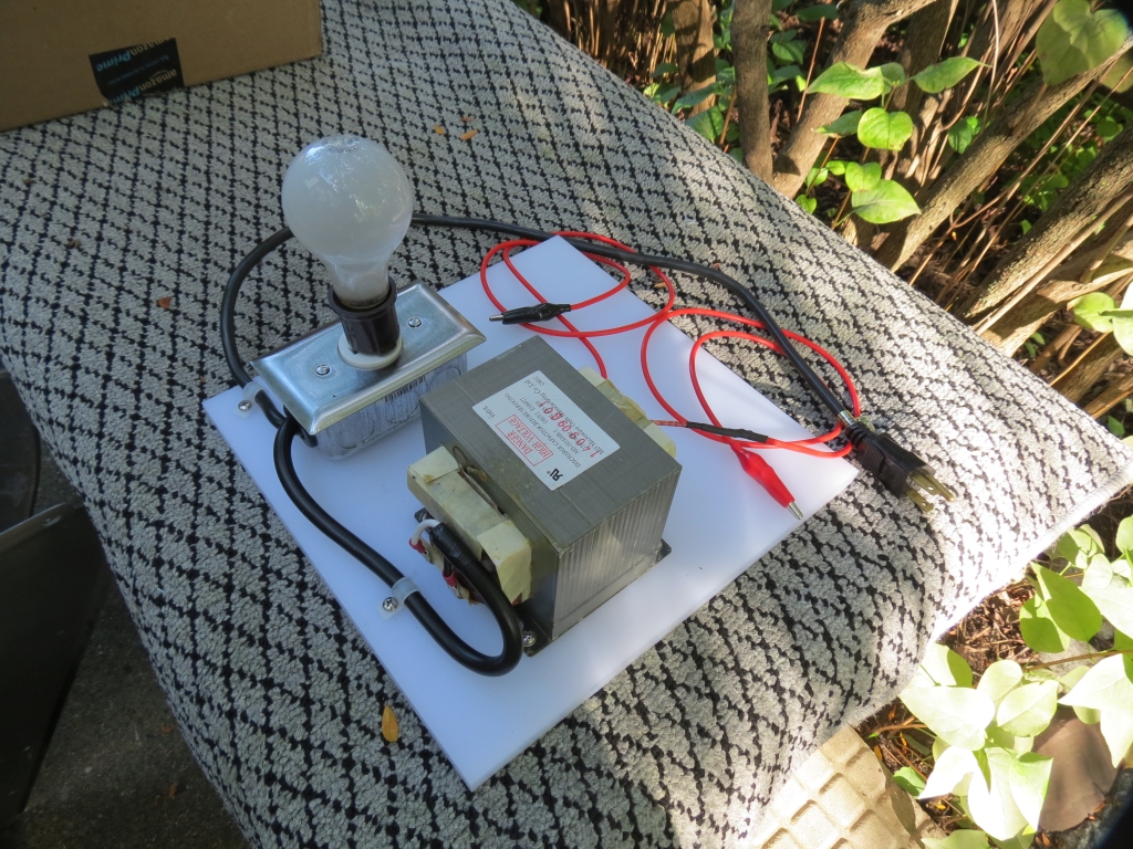
- IMG_2645sc.jpg (716.73 KiB) Viewed 11949 times
The 60W bulb (has to be incandescent) limited the current too much. I didn't have any higher wattage bulbs so I ended up plugging in a halogen work light, I'll have to check the wattage but it is either 300 or 500. This provide enough current for what you have seen in the video.
A better way would be a variac then you could adjust it but I don't have one (yet). This is an issue with microwave units but I think a neon transformer has shunts built in to limit current to set levels and a higher voltage and might be the better way to go.
I'll get pictures tomorrow of my set up which might clear a few things up. First let me say I am doing this outside. The whole thing is done on my driveway where I can control things.
I'm powering this from my 120V 20A shop power through a power strip that is fused at 15A and has a switch. I used screws into the wood then painted on salt water between the screw location. I attached the leads with the alligator clips shown. The wires are coming in from each end and are not next to each other or to me.
The high wattage lamp in plugged in to the series wired outlet and turned on. I then plug in the cord from the bread board to the power strip. At his point the light is out and the circuit has not yet been powered up. When I flip the switch on the outlet strip the light comes on and the process starts. It takes a little while before the burning starts.
As the burning starts to get together I have my finger on the switch and when they touch I power down. The light goes out and the burning stops. I then unplug the bread board circuit and detach the leads.
I used a tooth brush to clean some of the charred wood out and to get the salt solution off the board. That about did it for today's adventure.
Hopes this helps in your own quest for wood burning.
Ed


