Page 1 of 1
Today in the shop (a little look at the double tilt bases)
Posted: Sat Sep 23, 2017 11:12 am
by reible
This is just a quick look at the double tilt base upgrade from shopsmith. We are only going to look at the base and arms. I hope this will allow a better understanding of how this works for those who have yet to purchase them.
This will be in two parts. First we will look at the base and then at the arms in a second post.
The base is designed to take the 1-3/4 base tubes. The base is a universal if you will design and they are the same on both sides. Left and or right doesn't count anymore with these.
The base unit has a stop to control the depth of insertion of the tubes. You can actually by pass the stop if the tubes are at the right angle so yes you can get them too deep and of course to shallow.
So to start with this is how you can tell if you are about right. I started by inserting a tube up to the stop then added a piece of blue tape to the tube were it would show just how far in the tube was going.
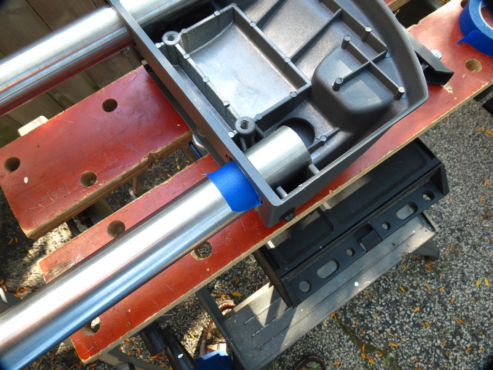
- IMG_4701sc.jpg (471.13 KiB) Viewed 7052 times
I then measured the distance.
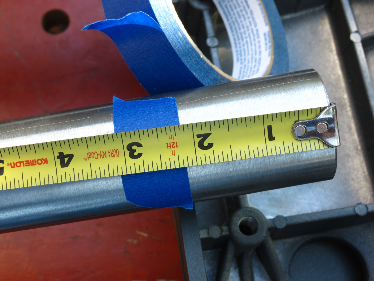
- IMG_4703sc.jpg (313.46 KiB) Viewed 7052 times
It will be about 2-1/8" in. I would not worry about a small difference but if it's off a lot something is wrong.
Next I insert both tubes into the stops.
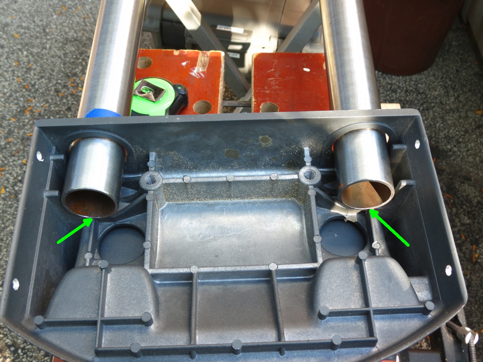
- IMG_4704sc.jpg (439.77 KiB) Viewed 7052 times
I then started the clamping process. I finger tighten the fasteners before applying a wrench. As you tighten the tubes are forced to the outside and up (unit is upside down in the pictures so flip your thinking around about up and down).
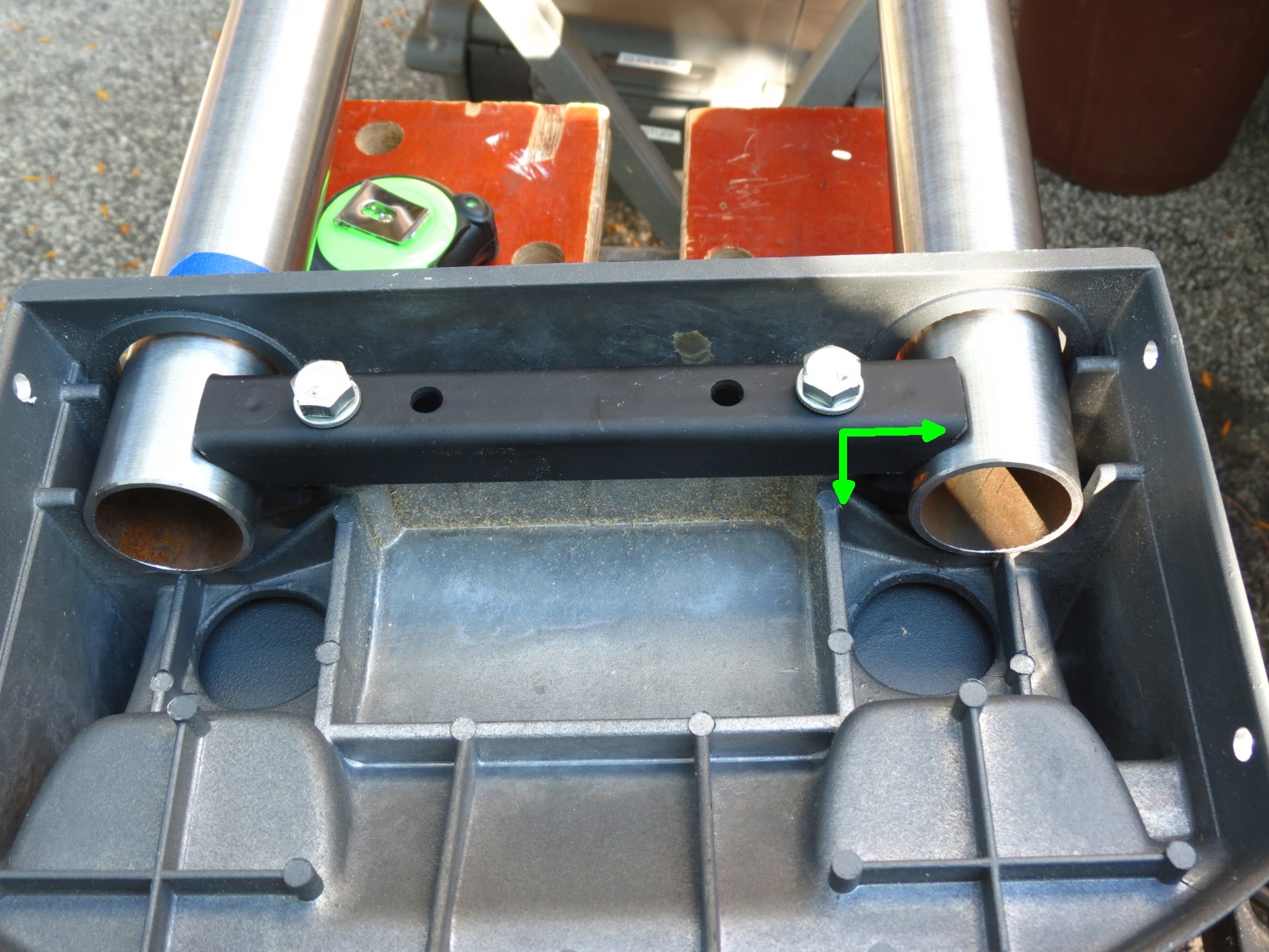
- IMG_4705sc.jpg (414.4 KiB) Viewed 7052 times
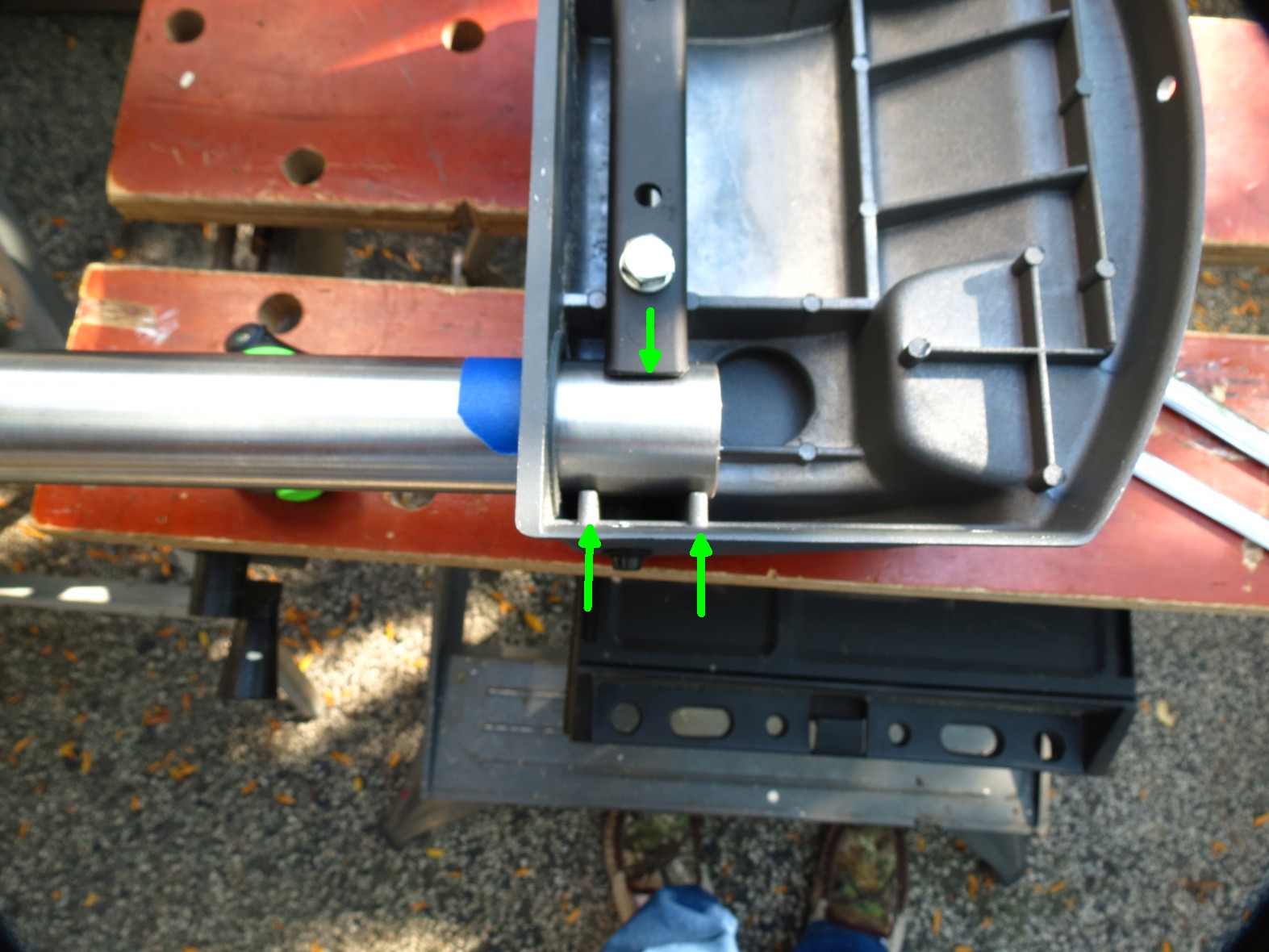
- IMG_4706sc.jpg (295.97 KiB) Viewed 7052 times
Again the other end looks the same.
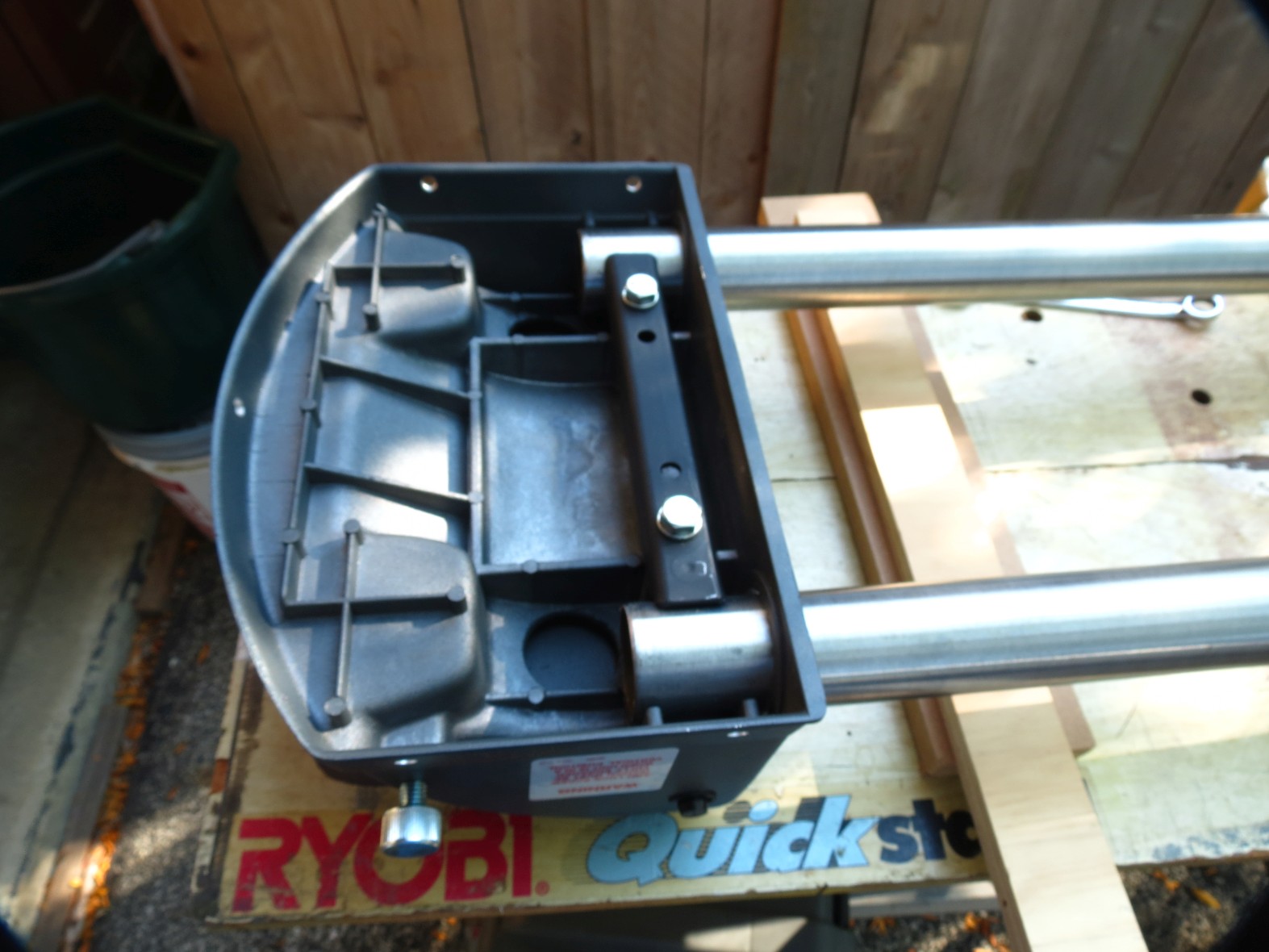
- IMG_4707sc.jpg (247.13 KiB) Viewed 7052 times
When you look at it from the tube side it should look like it is not centered in the hole but instead up and to the outside. Note the unit is now upright.
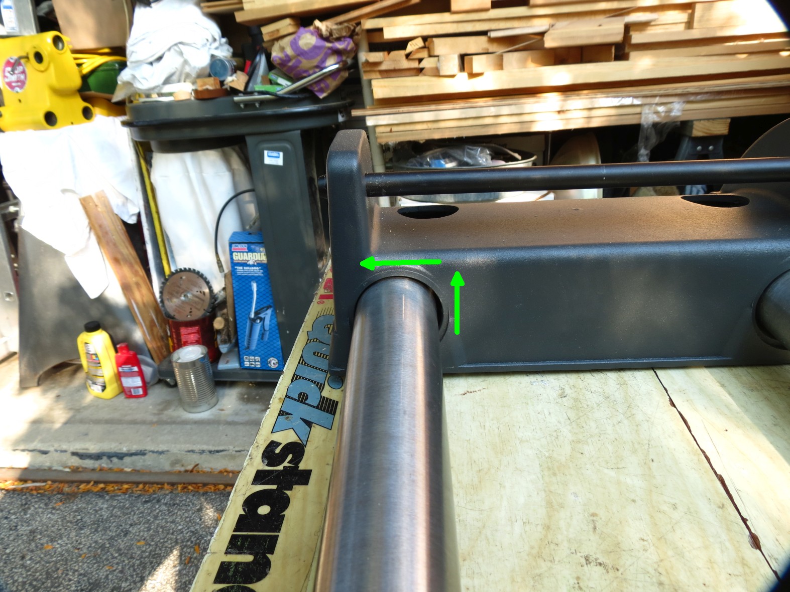
- IMG_4708sc.jpg (396.84 KiB) Viewed 7052 times
I'll be gone a good portion of the rest of the day but will try to add the second post yet today.
Ed
Re: Today in the shop (a little look at the double tilt bases)
Posted: Sat Sep 23, 2017 11:45 am
by everettdavis
As usual, very well done!
Everett
Re: Today in the shop (a little look at the double tilt bases)
Posted: Sat Sep 23, 2017 3:59 pm
by reible
Got just a few minutes between things so I'll see if I can get this second post done now.
In this post we will be looking at the arms and way tubes. There are only end stops in the arms and thus there is some play involved. So we will start like we did with the base and see how deep the tubes can go. Same tape trick.
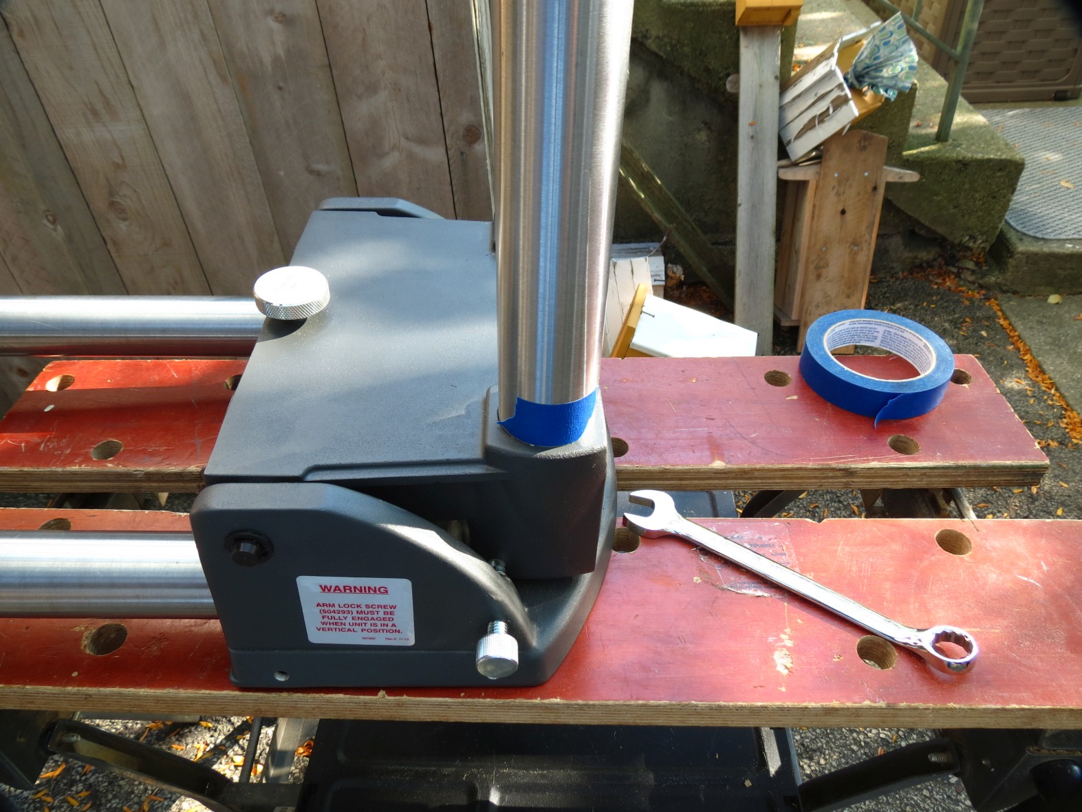
- IMG_4709sc.jpg (415.73 KiB) Viewed 7021 times
And again we can measure how deep they go.
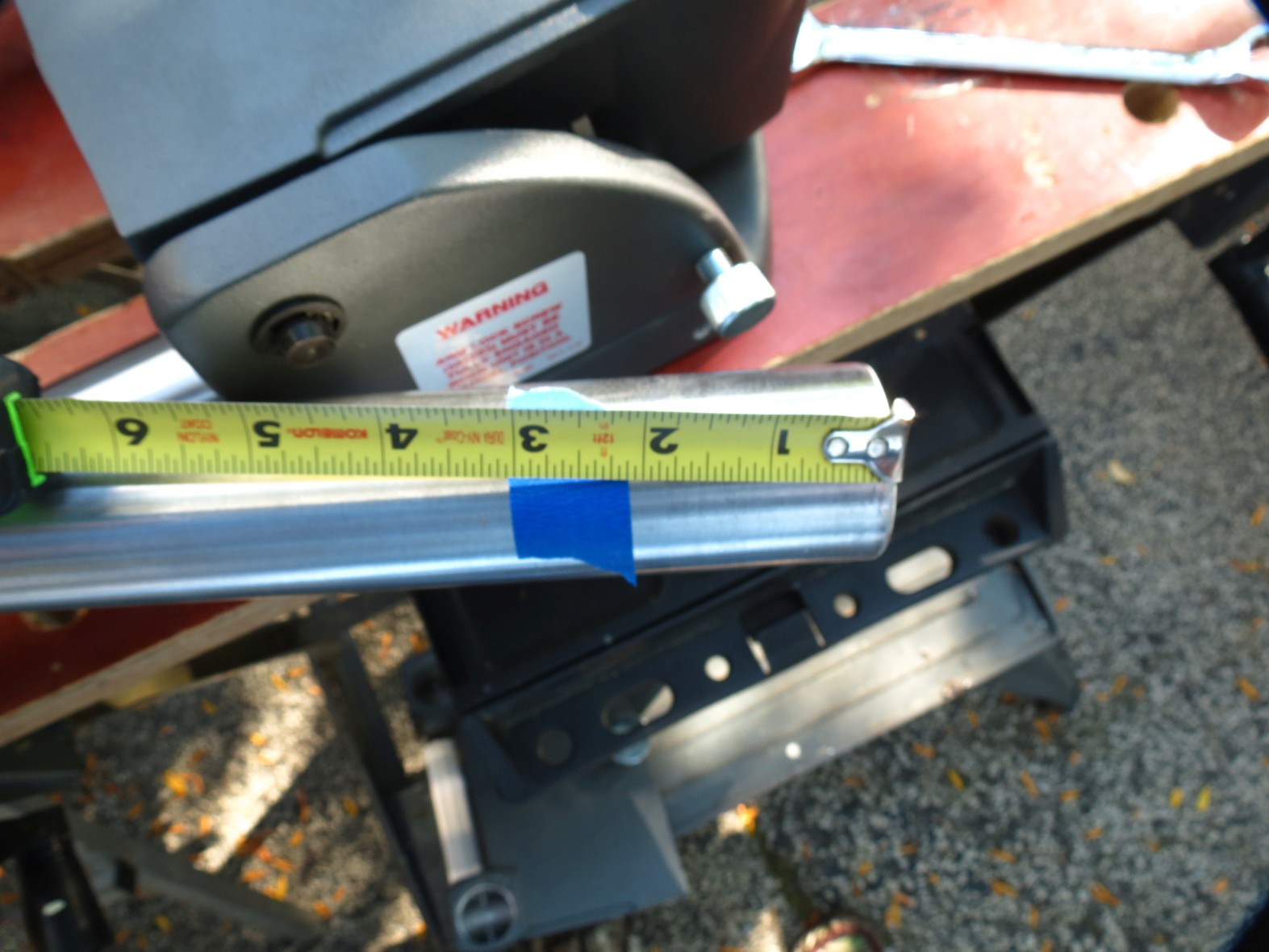
- IMG_4710sc.jpg (265.64 KiB) Viewed 7021 times
At this point I like to try and balance the insertion depth, not sure how importation that is but that is what I do. To achieve this I use a wax pencil and mark 3" in on both sides of the tube and mark both tubes that way.

- IMG_4712sc.jpg (394.62 KiB) Viewed 7021 times
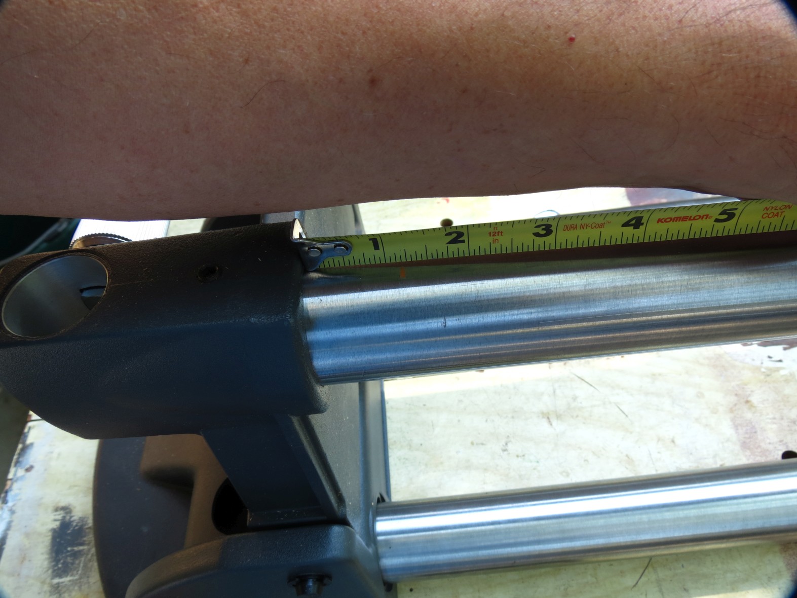
Now install the tubes in the arms. I have one arm attached and then slide on the other arm and then lower and lock it. I then slide the tube to one of the sides, in this case it was to my right. The I can measure from the arm casting to the wax pencil line.
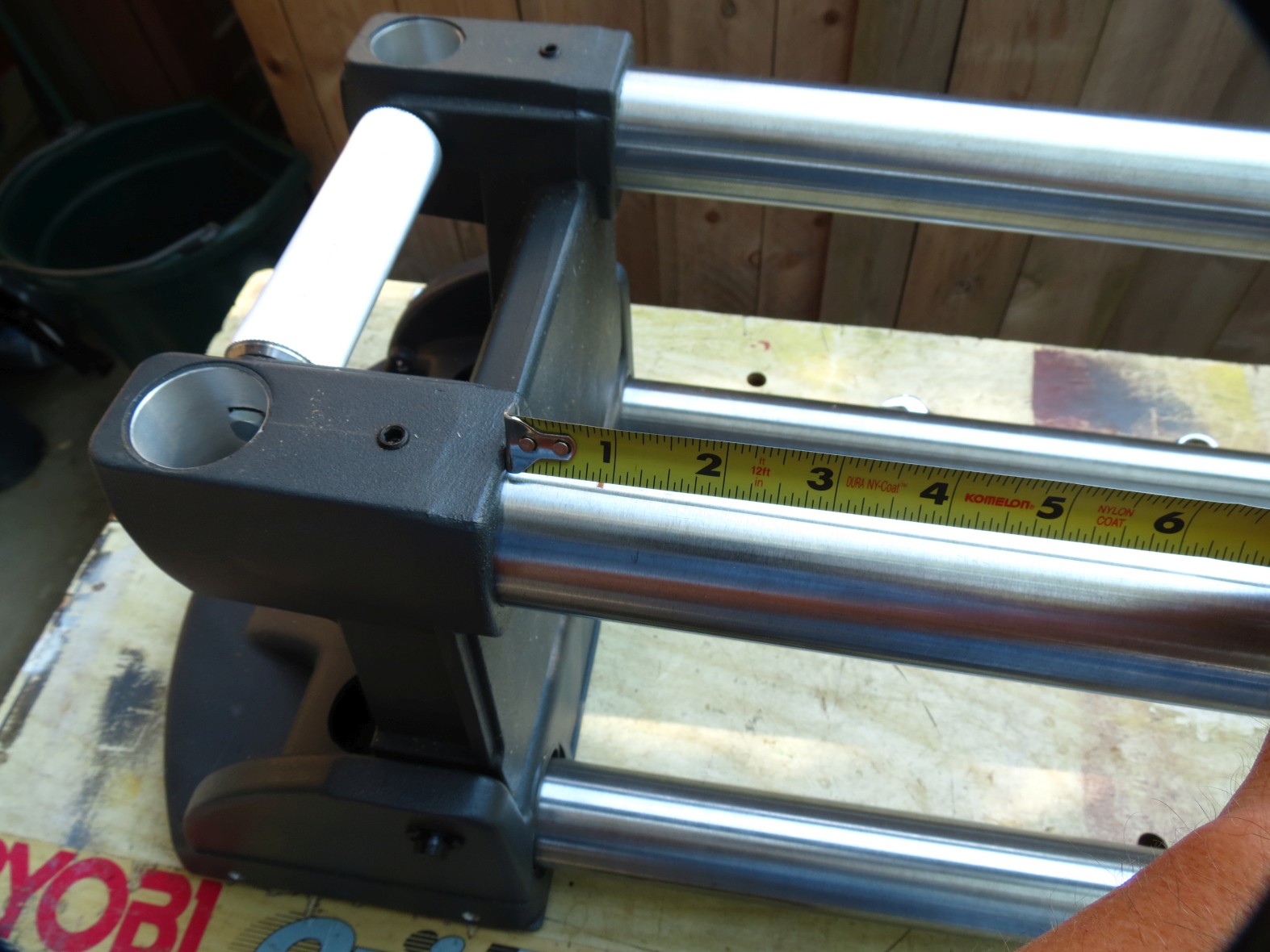
- IMG_4713sc.jpg (274.54 KiB) Viewed 7021 times
The measurement reads about 7/8". I go to the other end and measure again.
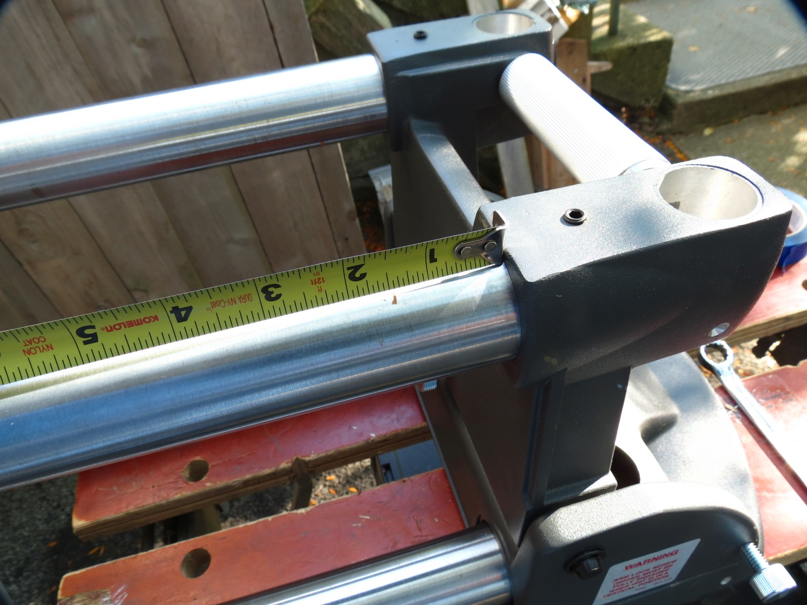
- IMG_4714sc.jpg (341.38 KiB) Viewed 7021 times
It is reading about 1-1/2". Now simple math says the difference or you can slide and measure a few time until the readings are the same. For me the math said the difference is 5/8" and that means an adjustment of 5/16" so there you go.
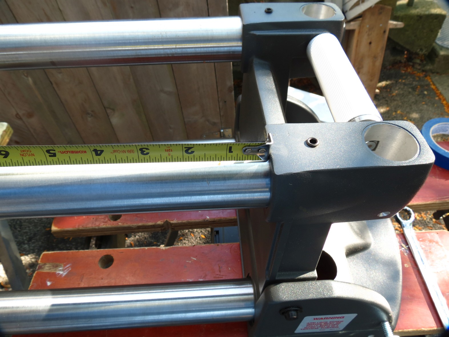
- IMG_4715sc.jpg (333.17 KiB) Viewed 7021 times
- IMG_4716sc.jpg (297.7 KiB) Viewed 7021 times
I now tighten the set screws on one end. It will be pretty close or even work at this point but to be safe I test it to make sure it lifts cleanly. Snug the setscrews and test again.
Either adjust or if you are happy tighten those two screws unless you have parts to add like I like to do. I do all of this without the headstock or carriage mounted because I find it easier for me to get things right. But each to their own on that. Any way it is at this point I add the other parts then put the arm back on and adjust the tilt.
So this it it for this unless people have questions.
Ed
Re: Today in the shop (a little look at the double tilt bases)
Posted: Sat Oct 21, 2017 9:27 am
by number3456
appreciate the info.I am curious as to the block of wood inside one of the tubes. Is it to keep the tube from being crushed?
Re: Today in the shop (a little look at the double tilt bases)
Posted: Sat Oct 21, 2017 11:06 am
by reible
number3456 wrote:appreciate the info.I am curious as to the block of wood inside one of the tubes. Is it to keep the tube from being crushed?
The "wood" is just a stream of sunlight. If you look at the two photos that show the same area one does look like there is something there but nope just a trick of nature.
Ed
Re: Today in the shop (a little look at the double tilt bases)
Posted: Sat Oct 21, 2017 12:15 pm
by dusty
Up to this point I followed pretty much the same procedure. I deviated just a bit BEFORE tightening the bolts and set screws. I made certain that the Bases both sat flush on a flat surface. Without doing this, it is possible to have a slight twist in the tubes resulting in them not all being in their proper planes.
I found that this aided somewhat in creating a base that will support end-to-end changeability of extension tables. I also believe that it eases later table alignment.
Just don't forget to secure everything and then double check to make certain that nothing moved.
Re: Today in the shop (a little look at the double tilt bases)
Posted: Mon Sep 28, 2020 11:59 pm
by DLB
I just noticed that the newer Double Tilt Bases are different compared to the photos in this thread, and I'm curious to know what the differences are. But of course I don't have the kind shown in this thread. Mine, purchased early this year, look like this:
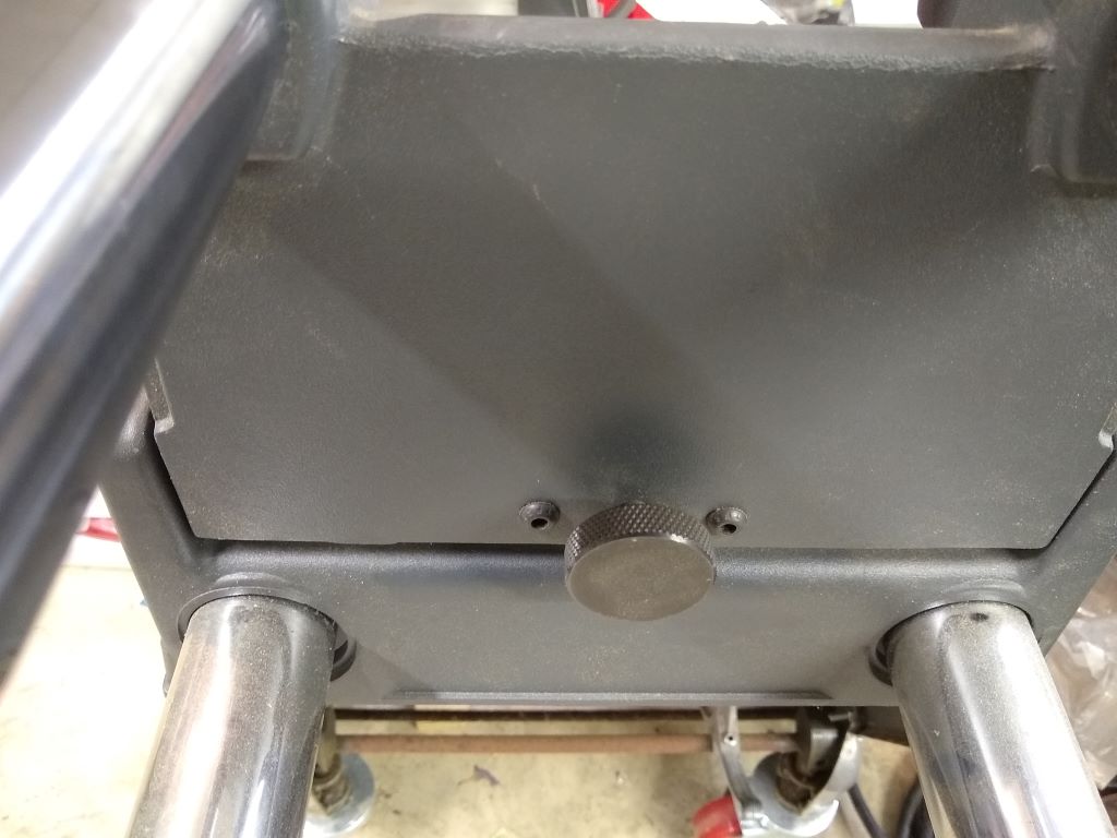
- DT Base
- IMG_20200928_221934541.jpg (3 MiB) Viewed 2050 times
Note that the knob is black (trivial) but also note the two screws next to the knob. There purpose is evident here:
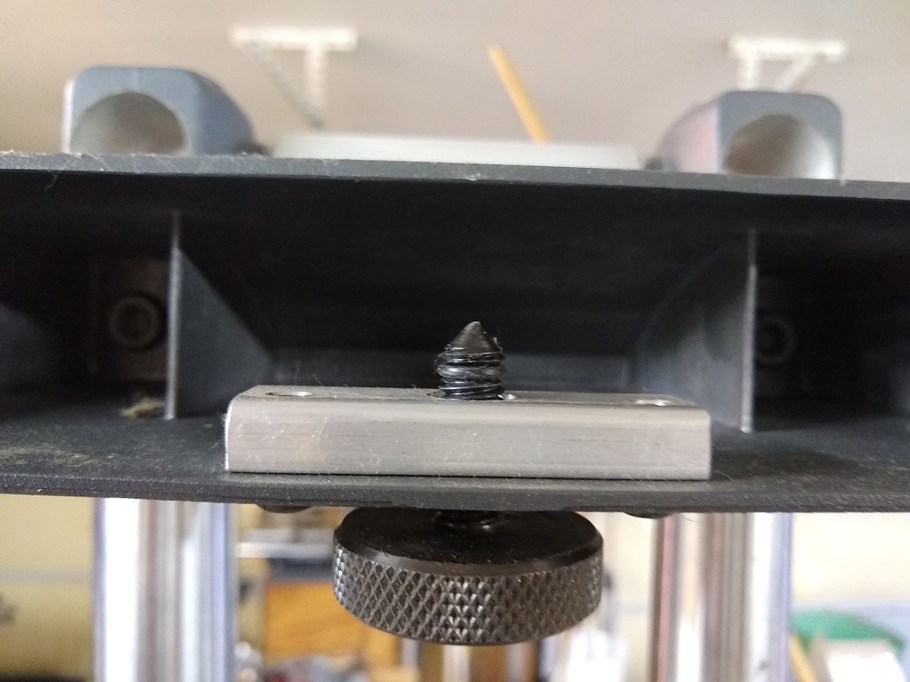
- DT Lockscrew
- IMG_20200928_222223318.jpg (165.22 KiB) Viewed 2050 times
They hold the aluminum plate that the lockscrew is threaded into. My question is, what do those lockscrews thread into on the previous style, and how is it held to the base casting? In case it is of interest, mine are double start threads, it is roughly one full turn from all the way in to all the way out. There is an o-ring on the threads, you can see it in the second pic, to change the feel when it is backed out.
Also kind of wondering if this is a producibility type change or if there might have been problems and this is an 'upgrade.' Any problems with those?
- David