Page 1 of 3
PowerPro Input Power
Posted: Mon Jul 19, 2021 11:31 am
by DLB
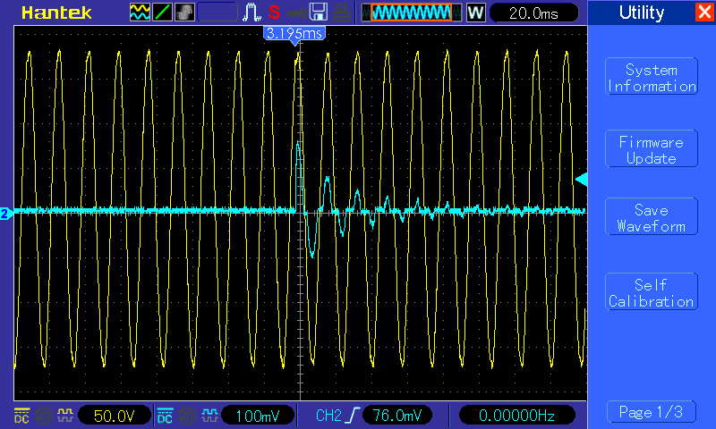
In another recent thread the subject of PowerPro in-rush current came up. There was a degree of conjecture involved. I have the three major items needed to introduce some fact into that discussion, though I've never used them together. The measurements involve a PowerPro, an Oscilloscope (O'scope) and a current probe for the O'scope. My first post is intended to describe the setup and explore if/how I can upload measured data to this forum.
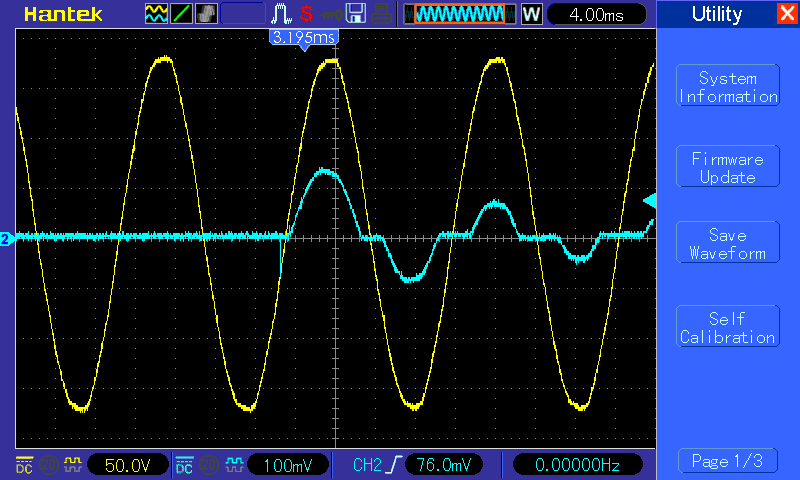
The PowerPro is dual voltage, I used 115 VAC for my measurements to level the playing field with a conventional headstock. (Some time ago BuckeyeDennis created a thread based on using a similar setup with a conventional headstock that I found very informative.) I would have preferred to connect to line voltage downstream of the switch, but the PowerPro is packed significantly tighter than the conventional headstock. So I made both the voltage and current connections in a short extension cord I modified for instrumentation and triggered off of current. Unlike the O'scopes of my youth, this works fine with a sampling scope. Also, my scope is not as cool as some. I don't see an obvious way to make the current channel display in Amps. My current probe has a couple of ranges and was set to 1mV/100mA for these. (Therefore, assuming math, 100 mV per major division equals 10A per.)

- PowerPro current 1
- pic_20_2.gif (26.36 KiB) Viewed 944 times

- PowerPro current 2
- pic_20_3.gif (20.18 KiB) Viewed 944 times
The upload seems to work for me with the gif's but not bmp's, the images seem fine. I'll do some additional evaluation with time base on the O'scope and with longer off-time for the PP. These worked as I intended, I adjusted the trigger level so that it triggered once and only once per power cycle. (Assuming I did not turn the motor on.)
Some initial thoughts: The input current does not closely resemble a sine wave as discussed in the other thread for 'Power Factor Correction.' Later I'll add a trace with the PowerPro consuming somewhat more input power. Max in-rush is going to take a bit of work because of multiple potential contributing factors. I don't think the above is representative, in fact the second trace might be close to best-case.
- David
Re: PowerPro Input Power
Posted: Mon Jul 19, 2021 11:43 am
by RFGuy
David,
I always enjoy looking at o-scope plots, particularly color ones like this, but I guess I am missing the goal here. Maybe I missed the relevant thread (or I am just dense), but just curious what you intend to measure on the PowerPro with this setup and why. Intrigued...
Re: PowerPro Input Power
Posted: Mon Jul 19, 2021 12:00 pm
by JPG
IIUC that is reasonable for no load(minimal) conditions at the output of the power supply. I.E. initial transient current at power on.
Re: PowerPro Input Power
Posted: Mon Jul 19, 2021 12:23 pm
by RFGuy
Is this in reference to the discussion on switch arcing (
viewtopic.php?p=285853#p285853) thread? Keep in mind if you are trying to measure in-rush current that probe impedance can affect your ability to capture this transient. The actual transient could be even larger than what you are showing here. In the past for these kinds of measurements, I have had to use an active high-Z probe to measure voltage across a 1ohm inline resistor to get an accurate capture of transients such as in-rush current. I don't say this to nitpick, but just to point out that the in-rush current could be even larger than what you are able to measure here due to equipment limitations...
Re: PowerPro Input Power
Posted: Mon Jul 19, 2021 12:30 pm
by Majones1
DLB wrote: ↑Mon Jul 19, 2021 11:31 am
…in fact the second trace might be close to best-case.
- David
How is the second trace different from the first trace? It looks to me like it’s the same sine wave with the time just zoomed in from 20ms to 4ms. Am I reading this wrong? (It “has” been 25 years since I used an o’scope on a regular basis.)
Re: PowerPro Input Power
Posted: Mon Jul 19, 2021 1:49 pm
by DLB
Majones1 wrote: ↑Mon Jul 19, 2021 12:30 pm
DLB wrote: ↑Mon Jul 19, 2021 11:31 am
…in fact the second trace might be close to best-case.
- David
How is the second trace different from the first trace? It looks to me like it’s the same sine wave with the time just zoomed in from 20ms to 4ms. Am I reading this wrong? (It “has” been 25 years since I used an o’scope on a regular basis.)
The two traces are similar but not the same. What I was referring to is that it appears to me that in the second trace I coincidentally turned the PP on very close to the time that the AC Input was at '0 crossover'. So there was no voltage potential at that instant and no in-rush current to speak of, resulting in something approximating a half sine wave. I expect a different result if I switch power on at or near the time when AC Input is at peak (+ or -). I included the first trace only to show how rapidly power demand diminishes in the normal startup.
- David
Re: PowerPro Input Power
Posted: Mon Jul 19, 2021 2:33 pm
by DLB
RFGuy wrote: ↑Mon Jul 19, 2021 12:23 pm
Is this in reference to the discussion on switch arcing (viewtopic.php?p=285853#p285853) thread? Keep in mind if you are trying to measure in-rush current that probe impedance can affect your ability to capture this transient. The actual transient could be even larger than what you are showing here. In the past for these kinds of measurements, I have had to use an active high-Z probe to measure voltage across a 1ohm inline resistor to get an accurate capture of transients such as in-rush current. I don't say this to nitpick, but just to point out that the in-rush current could be even larger than what you are able to measure here due to equipment limitations...
To an extent it is about that thread, because it made me curious. In that thread Dennis made a comment that it might make sense for the PowerPro to wire the switch contacts in parallel, rather than in series. The idea being to reduce the effects caused by arcing from contact bounce combined with in-rush current. I agree with him, but because the PowerPro is dual voltage I will retain the series connection that switches both power conductors. Intuitively I expect the PowerPro main power switch to have a long life. (Partly because it isn't used very often.)
I appreciate the input above. My current probe is 'active' but it is a relatively cheap clamp on probe. I don't know the probe's limitations specifically. I was mostly interested in seeing if there was any evidence of something other than R and C controlling in-rush. And generally curious about the PowerPro. I've used o'scopes quite a bit but rarely for current measurement.
- David
Re: PowerPro Input Power
Posted: Mon Jul 19, 2021 2:44 pm
by JPG
Both traces make sense. Both traces demonstrate increasing delay EACH cycle of current commencing AND the reduced magnitude in successive cycles.
The difference between traces 1/2 is indeed the coincidence of "on" occurring at voltage zero crossover in the second which exhibited a gradual leading edge current whereas the first exhibited a rapid current increase due to the transient application of voltage as the power was applied by the switch closure at a non-zero value.
Re: PowerPro Input Power
Posted: Mon Jul 19, 2021 11:46 pm
by BuckeyeDennis
Nice waveforms! I have neither a PowerPro nor a scope and current probe at my disposal currently, so thanks for measuring and sharing.
The current waveforms look to me as if the power-supply has a conventional (non-PFC) rectifier, and I’ve looked at hundreds of them. But the inrush current is much smaller than I’d expect with a fully-discharged capacitor bank. It appears to be about 15A peak, and the voltage is about 175V peak. So if the capacitor bank was fully discharged, the input resistance would have to be north of 10 Ohms, even allowing for substantial voltage drop across the switch contacts and the rectifier.
But to achieve its 1.75 hp rated output power, the PowerPro is going to have to draw maybe 15 Arms at full 120 VAC line voltage. There’s no way it can do that with 10 Ohms of input resistance. Which initially had me suspecting that the capacitor bank wasn’t fully discharged when you took those measurements. However, the second waveform shows initial current flowing when the line voltage was still very low, which indicates that the capacitor bank was fully discharged.
Do you have something that you could use for a rough current-probe calibration? Maybe a resistive heater or an incandescent light bulb, preferably with the current measurement checked against a DMM?
Re: PowerPro Input Power
Posted: Tue Jul 20, 2021 12:52 pm
by DLB
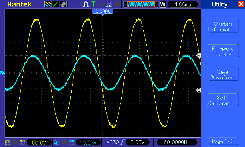
At step 1 of a 'rough calibration' I found the scope (not the probes) had some strange offset behavior on both channels. So it looked like my incandescent lamp power had both AC and DC components, even if AC coupled. The offset varied with V/div, but neither predictably nor monotonically. I ran the self calibration on the scope, which eliminated the problem. So now I've done the rough calibration suggested, but a grain of salt is needed to relate it to the pre-calibration scope traces. I used a 130V 90W lamp as a test load. Two DMMs, one clamp on (0.62A on the 'low' 60A scale) and one in-line (0.66A on a 10A scale). The current probe measured:

- pic_28_2.gif (21.19 KiB) Viewed 811 times
To maintain integrity with the PP setup I used the 1mV/100mA probe setting, and reduced V/div. The measurement window, which I haven't determined how to save with the trace, says 7.60 mV RMS, so 0.76A RMS. Interesting: Just noticed there seems to be a phase shift between E and I.

Scratching my head on that for now. I'll try a different bulb. I'll be disappointed if my current probe introduces uncorrected phase shift.
- David