Page 1 of 2
501325 Sheave - Control Assembly Shopsmith VII
Posted: Thu Oct 24, 2024 7:56 am
by jafpanda
This is a discussion to document the
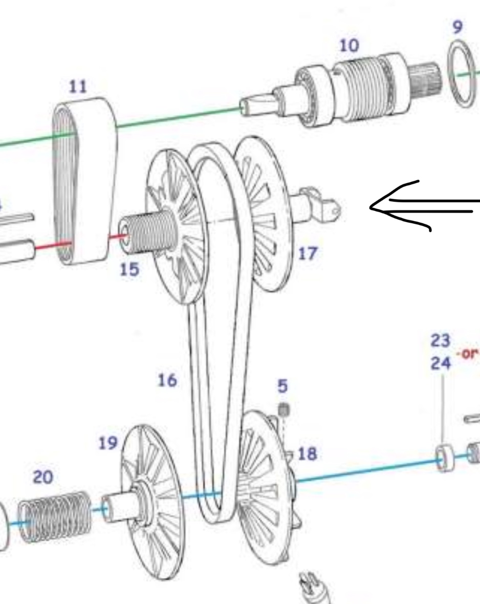
PN 501325 Sheave - Control Assembly (# 17) on a 2D drawing and 3D CAD model.
Again, same question as the CAM discussion… anyone interested in this topic?
.
.
- IMG_6771.jpeg (136.16 KiB) Viewed 41339 times
Re: 501325 Sheave - Control Assembly Shopsmith VII
Posted: Thu Oct 24, 2024 12:37 pm
by dusty
jafpanda wrote: Thu Oct 24, 2024 7:56 am
This is a discussion to document the
PN 501325 Sheave - Control Assembly (# 17) on a 2D drawing and 3D CAD model.
Again, same question as the CAM discussion… anyone interested in this topic?
.
.
IMG_6771.jpeg
Yes, definitely.
Re: 501325 Sheave - Control Assembly Shopsmith VII
Posted: Thu Oct 24, 2024 1:23 pm
by jafpanda
I pulled this Sheave Control Assembly out of a trashed Mark VII headstock that someone must have dropped. The housing was broken and braised at the eccentric area.
The bearing is shot, so before removing it… does anyone have some words of wisdom?
I measured 0.030 in max air gap between the cam follower and brass sheave tube.
No telling if it was the OEM or a replacement bearing.
.
Re: 501325 Sheave - Control Assembly Shopsmith VII
Posted: Thu Oct 24, 2024 2:07 pm
by jafpanda
These next "CAM Follower" pictures are from 2010 for comparison.
The bearing (attached to the CAM Follower Stud/Post) in this picture seems to have a larger air gap than the previous one.
I believe it is the original OEM installation, however there are no measurements available.
I'll have to do some math to figure out what a rough estimate for the gaps are and then run some tests later for correlation.
The speed accuracy in RPMs of the Mark VII will be impacted by the distance that the bearing is set, on the CAM Follower Stud/Post, and the bearing set into the Sheave's Brass Tube. Hopefully, there is a hard-stop inside the brass tube; which would make things less complicated.
Also, note the photo of "CAM_Follower_Bearing_Attached.JPG" shows that the "inside" horizontal surface on the CAM Follower is ramped... that is, it is not flat; as viewed from near to far. As opposed to the photo, "CAM_Follower_1.JPG" which does not depict that feature.
Again, any comments or advice is appreciated.
.
Re: 501325 Sheave - Control Assembly Shopsmith VII
Posted: Thu Oct 24, 2024 3:45 pm
by JPG
Yes the "snout" has a smaller id that serves as a stop for bearing insertion.
The "ramp" is there to allow for the cam od variation across the follower. That requires proper orientation when assembling the follower to the cam. It also provides a better bearing surface against the cam.
Re: 501325 Sheave - Control Assembly Shopsmith VII
Posted: Fri Oct 25, 2024 1:25 pm
by jafpanda
Does anyone have information on the pitch of the sheave … or even the motor drive vee belt (507490)?
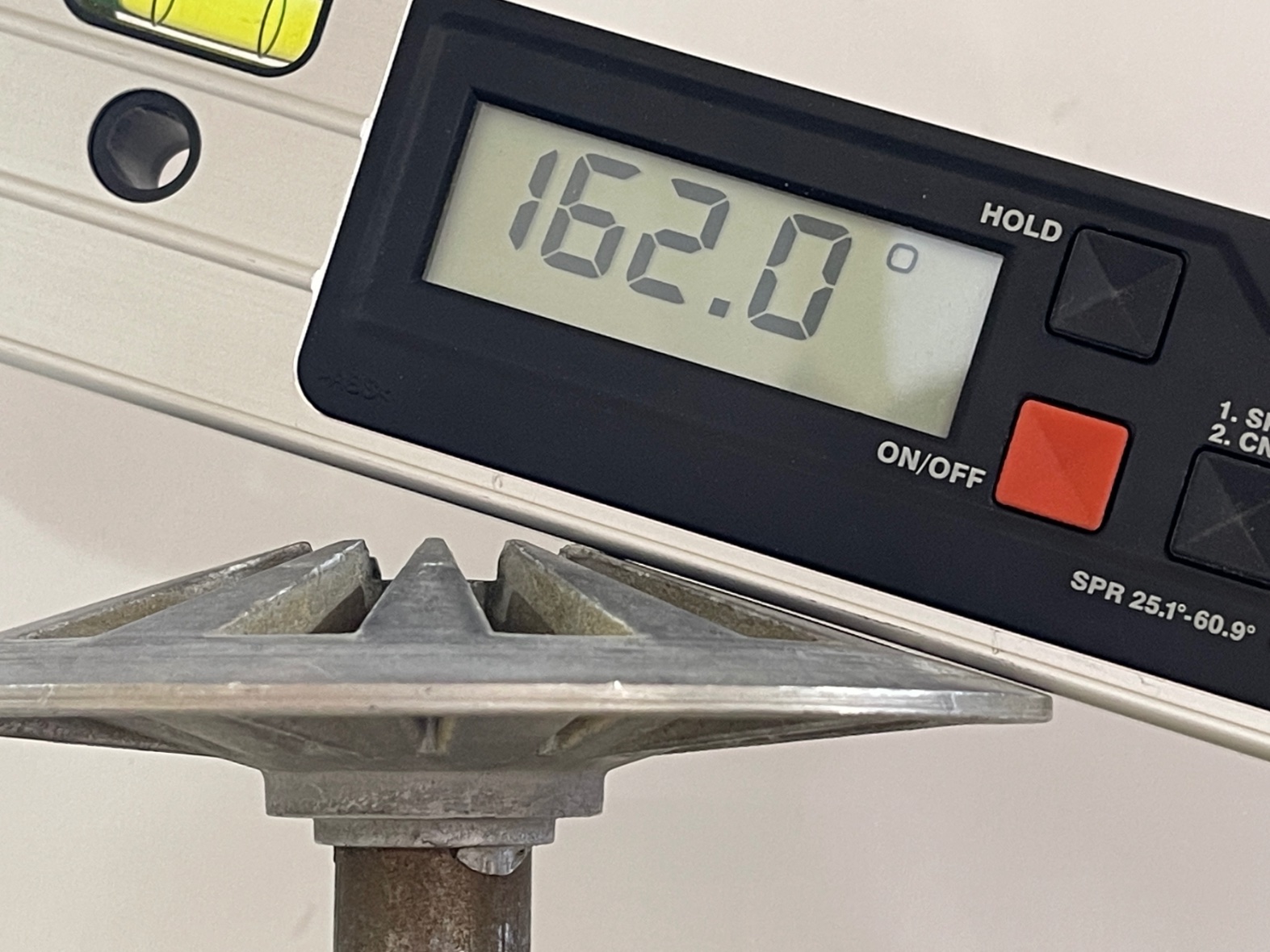
I’ve measured the worn sheave at 18 degrees (180-162). I’m guessing that the outer portion of the metal is least worn so I biased the measurement there.
I’m also guessing that the vee belt pitch (not loaded between the sheaves) is gonna be a larger pitch than the sheave… maybe by 2, 3 or 4 degrees.
.
- IMG_6832.jpeg (427.53 KiB) Viewed 41276 times
Re: 501325 Sheave - Control Assembly Shopsmith VII
Posted: Sun Oct 27, 2024 5:03 pm
by jafpanda
.
After messing around with just one sheave, it was time to do some "highly

scientific" measurements using a camera, 90 degree square, and both sheave halves on a shaft.
There were several pictures taken (only 3 of them were used) and imported them into Photoshop (for cleaning) and then imported them into Visio (for measurement).
Based on the photos (attached) and a single half sheave, I going to go out on a limb for now ... swag of 36 degrees for the 2-sheave pitch angle.
Again, I'm gonna take into consideration the spring force compressing the sheaves together; on the motor V-Belt (PN 507490).
So, the original v-belt design that was "released" probably used a 38 degree pitch.
At some point in time, Shopsmith went to a v-belt with a "4L 300 2300 J" specification. Perhaps it was a standard size and therefore a suitable substitute.
I'll look closer at the v-belt later.
As always, any comments, corrections, or polite suggestions are welcome.
.
Re: 501325 Sheave - Control Assembly Shopsmith VII
Posted: Mon Nov 04, 2024 11:40 am
by SteveMaryland
Responding to your PM, I used an angle of 19 degrees (= 109 degrees as measured from sheave axis). Measured from the physical components, not the original Shopsmith drawings.
Attached are illustrations. Modeled in Solidworks. Have IGES files of the sheaves but Forum does not accept them.
The above info is for Mark V. Not Mark VII. I doubt there is any relevant difference in the sheaves but who knows.
I don't understand why this angle matters much in a rebuild.
Re: 501325 Sheave - Control Assembly Shopsmith VII
Posted: Mon Nov 04, 2024 12:34 pm
by jafpanda
Wow... very nice drawing. Did you do this yourself ?
I did not think to measure from the shaft tube.
I'll remeasure it... see what I come up with.
I'm also thinking that the Mark VII sheve's originally used a custom v-belt in the early 60's. I'll also check the original belt dimensions (507490)
Re: 501325 Sheave - Control Assembly Shopsmith VII
Posted: Mon Nov 04, 2024 1:44 pm
by JPG
IIRC the MVII control sheave has a shorter 'snout'.