I hope you were able to buy just the Speed Changer and for a good price. The Model 10 it was with, in my opinion, is way overpriced.
Since it is the one you are going to have, what I said before applies. Not having it in hand yet, do check on the Oilite Bearings condition before replacing them. If they are okay keep the set you purchased from hogwinslow1960 as a spare. Keep them in the container they come in until needed. Removing the Oilite Bearings from the Pulley Assembly can damage the softer metal they are made out of.
A lot of what I have already posted has to do with the cleaning and disassembling the Speed Changer. Since you don't have it yet now is a good time to learn about it. This will give you a head start by learning about the Speed Changer, planning what needs to be done and how best to do it.
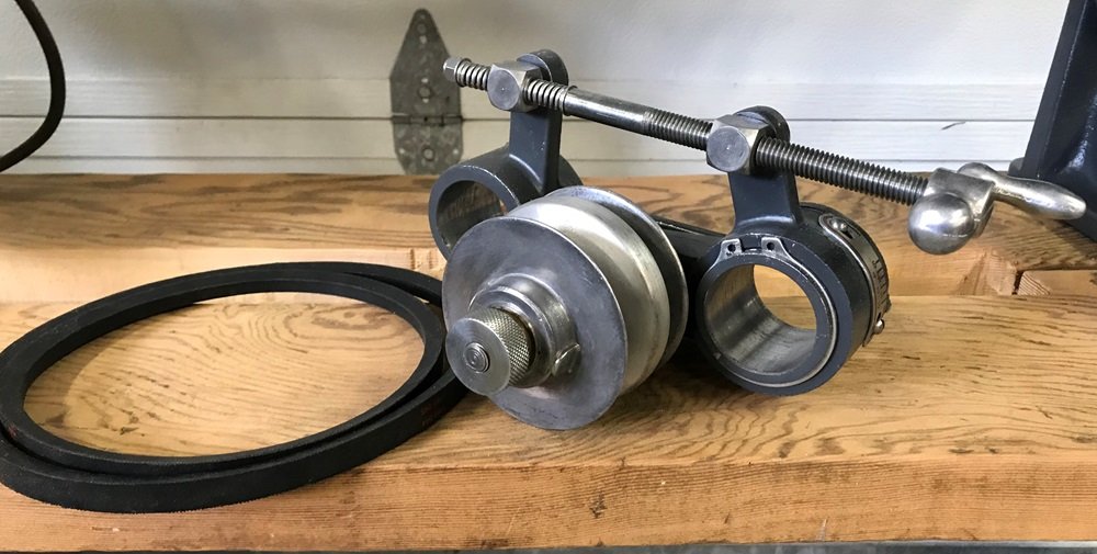
When it is time to reassemble it there are some things to know. When reassembling I put some grease on the Base Bracket before reinstalling the Pulley Arm. You don't want any binding of metal to metal here. I have used white lithium grease for this. When attaching the Screw Assembly do NOT completely tighten any of the three lock nuts. The two lock nuts for the blocks attached to the Base Bracket and Pulley Arm should not be completely tightened to allow the parts to move. The Springs on the end of the Screw Assembly should not be compressed. This is the reason having good lock nuts of this type is important. Now a word of warning, when using the Speed Changer NEVER try to turn the Screw Assembly past the point the speed no longer changes. To help protect when getting to the end of the speed range both high and low the springs are there to help avoid damage to the Base Bracket and Pulley Arm. The picture below shows that nut tightened way to much and is compressing the springs.
_
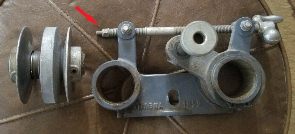
- Speed Changer nut tension arrow.jpg (91.31 KiB) Viewed 7606 times
.
The nut should be on only enough to have the locking end engaged on the threads and not compressing the springs much if at all. Below is what can happen if the Screw Assembly is turned too far after getting to the end of the speed range. This can happen even if the nut is not already compressing the springs.
_
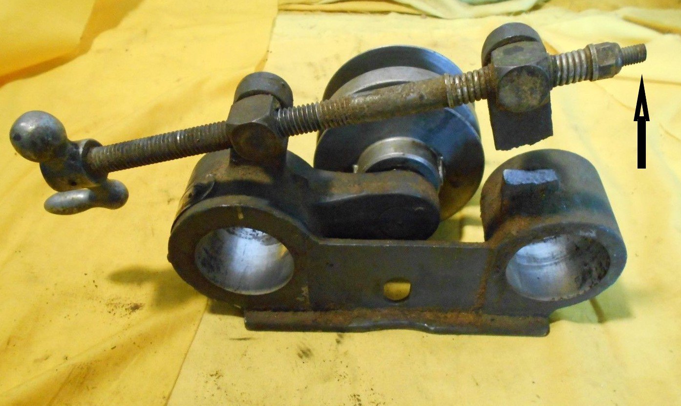
- broken ear arrow.jpg (179.54 KiB) Viewed 7606 times
.
The pictures of the two Speed Changers above have the Screw Assembly mounted inboard closer to the Headstock. Yours has it outboard. Outboard is the preferred position as the Crank Handle doesn't interfere with the Headstock Way Tube Lock.
Something I noticed on your Speed Changer is one screw is missing or broken off for the Speed Indicator. Find a screw comparable to the other one but if it is broken off you will have to remove the broken piece from the Pulley Arm. After removing that check to see the inside surface is free of any burrs so the Pulley Arm can still move freely on the Base Bracket.
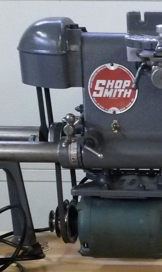
One challenge in reassembling the Speed Changer is setting the Pulley Assembly correctly. This is done by using the set screws to lock the outside sheaves in place. First put the Center Floating Pulley on the Sleeve with a bit of lightweight oil for lubrication. Using oil will not last as long as grease but is easier to reapply since it can be done without disassembling the Pulley Assembly. Do not over oil it as you don't want oil getting on the belts. When properly set the belts should have one riding even with the top of the pulley and the other almost touching the sleeve of the Floating Pulley Center. The belt should never ride down on the sleeve of the Floating Pulley Center. That will allow slipping if it occurs. As the belts wear readjusting the Pulley Assembly will be necessary. The picture below shows the Speed Changer in place. Note that the one belt is even with the top of the Floating Pulley. The other belt is down in the Pulley almost but not touching the sleeve of the Floating Center. When putting the Pulley Assembly on the shaft of the Pulley Arm use some lightweight oil for lubrication of the Oilite Bearings too.
_
- Speed Changer in place.jpg (88.63 KiB) Viewed 7606 times
.
The above Speed Changer has the Screw Assembly mounted inboard. You can see from this example how close the Screw Assembly Crank gets to the Lock Lever of the Headstock.
Another area of caution is when the Speed Changer is mounted on the Way Tubes and the long Headstock Set Screw has the nut to hold the Speed Changer against the Headstock is in place. Use caution when moving the Headstock on the Way Tubes making sure the Speed Changer is following without any binding. If the Speed Changer binds when moving the Headstock, the Base Bracket can easily be broken in half.
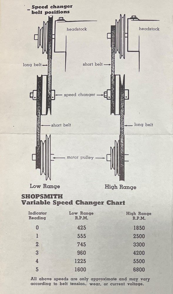
Below is a chart of approximate speeds and a diagram of the high and low setups.
_
- Speed Changer Pulley Diagram.jpg (106.64 KiB) Viewed 7606 times
.
Below is a restored Speed Changer.
_
- Speed Changer - Crank Outboard 17731.jpg (99.18 KiB) Viewed 7606 times