Page 1 of 3
Replacing Wires INTO the motor
Posted: Sat Apr 03, 2010 10:53 pm
by PG-Zac
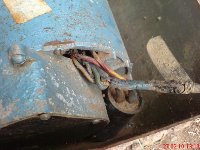
The wires going into my motor are fried, with brittle, cracked insulation, and a little evidence of arc burns. Somewhere in the past some idiot modified the wiring and apparently had little idea of what he was doing.

Tomorrow I think I'll open the motor to find out
IF I can salvage it. I really don't want to replace it, as the shipping costs to S.A. would put me on bread & water for a couple of weeks.
Has anyone here performed this brave act of maintenance before?
Can you give me some pointers before I venture into the depths?
Thanks.
Posted: Sat Apr 03, 2010 11:44 pm
by wannabewoodworker
I pulled my motor apart recently while rstoring my greenie and it wasn't a bg deal but mine was not the same as yours. The wires you show are similar to the ones on my motor but my wires go into the stator field windings on the motor housing and if those are shot I think you are SOL and will need a new motor. I am all for fixing anything and everything I can but that is something that isn't worth getting into. Unless those wires are connected to something that is easily re-done then I think a new motor is in order but you will be better at determining which way to go as I can't really see what is going on with those pics.
I picked up a 30' 12/3 contractors extension cord today to replace the cord in my Greenie. I cut the female end off and stripped back the outer insulation about 24" and then crimped on some connectors. Then I hooked it up to the motor to see if it would run as I never got a chnace to run it after buying as it was in bad shape. Well the motor ran fine in the vise but the switch is shot. I got a nice strain relief at Home Depot at the same time and drilled a new hole over the old hole and installed the strain relief before painting the motor pan and it came out super custom.
Wire Colour coding?
Posted: Sun Apr 04, 2010 9:30 am
by PG-Zac
I'd like to confirm what colours represent Live & Neutral going into the stator? I know our colour coding standards from the switch to the mains, but from the switch to the motor and the capacitor is a little unclear.
It probably won't make real difference in operation, but I'd like to get it right.
Just by the way, it looks like I may have burn damaged stator windings. We'll see when I test it after replacing all the wiring I can.
Posted: Sun Apr 04, 2010 10:58 am
by dusty
I've never tried to rewire a motor long distance but let's give it a go.
Looking at your photos, it appears that the capacitor is connected to a red wire and a yellow with red tracer wire. I also see those two wires coming out of the motor. I think those two are definite.
Coming out of the cord (with burned outer insulation) I think I see three wires. This is also what I would suspect one appears to be green, one is white or slate and the third is hard to tell but I would bet it is black.
If I am correct so far AND you are wiring this for 110 vac, this is a dead cinch. The green wires gets connected to the motor housing (safety ground). The remaining two wires (black and white) are the 110 vac power input and they get connected to the power cord with the black wire getting there via the switch (a SPST switch) while the white connects to white.
In some applications both the white (neutral) and the black (hot) get routed through switches usually housed in the same casing (this is a DPST switch).
Do you know that this motor worked before you did the tear down?
When you first apply power to this motor I strongly recommend that you NOT be touching the motor frame. Clamp it to your bench somehow so that when power is first applied the torque cannot move the motor. After the motor is running, check the frame of the motor with a meter to make sure it is not hot (shorted to power). I have been knocked onto my kester by not doing this.
In the absence of a meter, I have been known to check the chassis for "hot" by slapping it with the back of my hand. This is done so that if it is hot, the muscles do not involuntarily cause you to grasp onto what is hot. THIS IS NOT THE RECOMMENDED WAY.
Posted: Sun Apr 04, 2010 4:23 pm
by JPG
1) This is a 115/230v motor.
2) Wire colors from inside the motor are not necessarily the same as building wiring.
3) I just happen to have a Goldie with a 115/230v motor.
4) It just happens to be an A O Smith motor.
5) I just happen to have the rewiring instructions for converting between 115 and 230v.
.
.
.
.
.
What's it worth to you for me to 'share' this knowledge?:D
.
.
.
.
There are 6 wires that exit the motor.
Red connects externally to start capacitor.
Red tracer connects to second capacitor terminal.
The windings are split(dual voltage) so there are two pair of winding wires.
One winding has a Blue and a Black wire.
The second winding has a White and a Green wire. NOTE!!!!!! The green wire is NOT a ground!!!!!
For 230v connection, the black and green wire are connected externally(spliced).
The Blue goes to one side of a 2 pole switch.
The White goes to the other side of the 2 pole switch.
For 115v connection, the Blue and Black are spliced externally and connected to one side of a 2 pole switch.
The Green and White are spliced externally and connected to the other side of a 2 pole switch.
THE GROUNDING CONDUCTOR is connected to the motor frame externally.
The polarity of the line cord connection between the mains and the 2 pole switch does not matter. Here in the US, the polarity is only relevant if a single pole switch is used.(in which case the non-grounded(hot) wire is switched). Here in the US the grounded conductor is usually white(or slate). The grounding conductor is green or green with yellow stripe/tracer.
If this is not clear, pm me and I will attach a copy of the 'reconnection' instruction sheet to an e-mail.
P.S. The wires have rubber insulation and need to be replaced! This will probably involve use of a soldering iron. I have not(yet) done that to mine, so I am quite interested in what you 'discover' once you get inside.
Posted: Sun Apr 04, 2010 4:47 pm
by PG-Zac
dusty wrote:Looking at your photos, it appears that the capacitor is connected to a red wire and a yellow with red tracer wire. I also see those two wires coming out of the motor. I think those two are definite.
Correct - at the capacitor the wires are red and yellow with red stripe

But they both look red going into the stator - probably brcause of previous overheating.

dusty wrote:Coming out of the cord (with burned outer insulation) I think I see three wires. This is also what I would suspect one appears to be green, one is white or slate and the third is hard to tell but I would bet it is black.
Actually, the green wire you see has nothing to do with the power into the motor - It connects Stator windings, and is just wound in the insulation tape to tidy up the excess. The earth wire (ground) you expected to see is long gone.
The power cable coming into the motor is just a black & a white.

dusty wrote:If I am correct so far AND you are wiring this for 110 vac, this is a dead cinch. ... ...
In some applications both the white (neutral) and the black (hot) get routed through switches usually housed in the same casing (this is a DPST switch).
I will be installing a DPST switch, but this will be a 220/240 V power supply.
dusty wrote:Do you know that this motor worked before you did the tear down?
It definitely did not work. In hindsight it looks like I was stupid to try putting power onto this motor, but it is so bad that it couldn't even short out.

More to come in my next post - too bad we're limited to 4 graphics per entry.
.
Posted: Sun Apr 04, 2010 4:55 pm
by PG-Zac
JPG40504 wrote:
.
What's it worth to you for me to 'share' this knowledge?:D
.
Red - if you bring your butt here I'll kiss it.

JPG40504 wrote:If this is not clear, pm me and I will attach a copy of the 'reconnection' instruction sheet to an e-mail.
P.S. The wires have rubber insulation and need to be replaced! This will probably involve use of a soldering iron. I have not(yet) done that to mine, so I am quite interested in what you 'discover' once you get inside.
Your explanation is quite clear thanks, but just in case, I'd like a copy. I will PM you my email for you to send the instruction sheet - Thanks.
I have been taking lots of pics, & I'll post them with some explanation of the de-soldering operation soon. I have already de-soldered the capacitor because those wires were fried (at least the insulation was seriously brittle)
.
Posted: Sun Apr 04, 2010 5:20 pm
by PG-Zac
dusty wrote:
In the absence of a meter, I have been known to check the chassis for "hot" by slapping it with the back of my hand. This is done so that if it is hot, the muscles do not involuntarily cause you to grasp onto what is hot. THIS IS NOT THE RECOMMENDED WAY.
I don't like being bitten like that, so I use a wire with two naked ends and try to make sparks. This doesn't always save me from the bite, but it usually saves me from the worst shocks. Our domestic wiring codes require ALL circuits to pass through an "Earth Leakage" or "Ground Fault" trip switch, so If there is a short, the DB usually trips out before anything bad happens.
I think I may be flogging a dead horse here, as there seems to be some burn damage on the stator. Maybe its just superficial, maybe not.


While I'm breaking down the motor, I might as well take the opportunity to service the sheaves,

I successfully removed the first parts (no ping-gone)

But I can't get the fan sheave off the shaft even though I have loosened a set screw. Is there a trick I don't yet know, or is it the normal case of penetrating oil and careful force?
.
Motor Housing Damages
Posted: Sun Apr 04, 2010 5:31 pm
by PG-Zac
Just for interest, in the picture showing the capacitor's wires you can see where a piece of the casting has broken off.
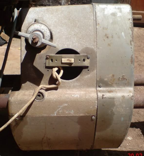
Well, there is also a piece broken off the plastic cover of the centrifugal switch,
but the worst is this long crack.

I just about soiled myself when I saw that.
Actually no problem, that is just a shadow line from a casting ridge.
NO DAMAGE.

.
Posted: Sun Apr 04, 2010 5:56 pm
by JPG
PG-Zac wrote:Correct - at the capacitor the wires are red and yellow with red stripe
But they both look red going into the stator - probably brcause of previous overheating.
The two 'red' wires at the top are NOT the wires going to the capacitor. They go to the start switch.
Will a photo copy do we kissing???:D
That black winding does NOT look good!!!!:(
P.S. You might want to check the diameter of the main shaft pulley. IIUC models destined for 50 z have a larger pulley(more recent one any who). Since yer motor is 50/60 Hz 1963 vintage, it probably does not! If you have 50Hz, you might want to replace the pulley. That would allow it to operate in the 'normal' 700 - 5200 rpm range.