billparker wrote:Now that the holidays are pretty much over, I've got some questions regarding the speed control. I purchased a new pork chop quadrant while maintaining the remainder of the control that came with the used SS. I did incorporate Bill Mayo's mod that replaces the quadrant pin with a small bolt with a nylock nut. I've attached 4 photos of the control after it was modified. I remounted it in the headstock without attaching the sheave to the quadrant.
When moving the speed control handle thru the speed range from Fast to Slow, more force is required in the mid-range portion of the travel. The mid-range seems be binding while the Fast and Slow regions seem to not require as much effort to turn (normal force, I would say).
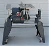
I haven't used a SS in many years so I don't really know what to expect. I never saw the innards of my first SS so I don't know what the Speed Control rack and pinion should look like, especially how they are aligned when new. The gears don't seem to be aligned in this unit as shown in the attached photos. I thought maybe someone could look at this and tell me if the gear alignment looks "normal".
I hope this makes sense.
Thanks,
Bill:o
The worm gear is slightly cocked(to the left in your pix). Actually it is the legs that are out of line.
A word of caution. The legs are easily broken if over stressed, so what follows must be done cautiously.
Remove the porkchop, secure the speed control in a vise so that the legs can be moved about 1/16" to the LEFT(corrected) as indicated in your pix. DO NOT try to move all at once. Gently pull them a small amount at a time. Make sure you do not slip and over bend them. Pull the rightmost leg first, then the other one the same amount. Ideally the porkchop will just barely fit between the legs. EDIT = looking again at your pix, the left leg looks like it is bent to the right.
I like to file the mating surfaces slightly just to true them up(flat).
If the legs are too far apart to begin with(the screw is pulling then together), a washer between the leg and porkchop will reposition the porkchop and may be preferable to attempting to bend the legs.
If there is a high spot where the porkchop binds against the worm gear, judicious filing of the
worm gear teeth that are binding may help. <<<<< edit
Quadrant gear teeth, NOT the Worm gear teeth
I had this problem with the last 'new' porkchop I installed. A very small amount of interference causes it to get stuck.
If the binding is slight, normal use will 'work it out'(the porkchop is soft and will coldflow(?) and relieve the binding over time).
P.S. I am referring to the last two pix re left/right positioning.