
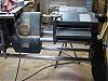
I have had a similar situation and can not get it resolved. In my situation it looks like the entire machine is racked but I can figure out where. The bench tubes are inserted into the casting up to the stop. I can align the extension table on the right but no way can I get to align on the left. The table wants to move forward (toward the operator) when installed on the left side. Also when I install the extension table in the left end of the machine there is a very noticeable downward tilt of the table in the direction of the headstock.
In the first pic you can see how the table moves forward to the operator when installed on the left end
[ATTACH]18223[/ATTACH]
The second photo shows the rear rail of the extension of the table
[ATTACH]18224[/ATTACH]
The third photo shows the definite downward (toward the headstock) tilt of the table and support tubes when the table is on the left end of the machine
[ATTACH]18225[/ATTACH]
This photo shows proper alignment on the right side of the machine.
[ATTACH]18226[/ATTACH]
Any suggestions?
The reason that I am posting this again is that my offset appears to be similar amount to Al's
Bill V
PS all pics are from the rear of the machine.
Can You Get Perfect Horizontal Alignment By Squaring the Headrest?
Moderator: admin
-
JPG

- Platinum Member
- Posts: 35598
- Joined: Wed Dec 10, 2008 7:42 pm
- Location: Lexington, Ky (TAMECAT territory)
IMHO the tailstock(with offset eccentric) is a potentially faulty reference. I suggest using an extension table (or preferably the legs only) to establish the mid point between the spt mount bores. IIRC(I be in TN away from SSstuff) the bench tubes do NOT have a stop. The way tubes DO have a stop tn the right end casting and the tie bar.
The way tube length is compensated for by the clamp length adjustment.
The adjustment by twisting the legs will require gorilla mode (or a 2x4 lever) to move significantly.
The idler shaft eccentric(belt tension) should not have any effect on the main shaft positioning.
P.S. Do newer MV's have stops for the BENCH tubes in the end castings???? IIUC, stops were added with the Mark 7 DT version.
╔═══╗
╟JPG ╢
╚═══╝
Goldie(Bought New SN 377425)/4" jointer/6" beltsander/12" planer/stripsander/bandsaw/powerstation /Scroll saw/Jig saw /Craftsman 10" ras/Craftsman 6" thicknessplaner/ Dayton10"tablesaw(restoredfromneighborstrashpile)/ Mark VII restoration in 'progress'/ 10E[/size](SN E3779) restoration in progress, a 510 on the back burner and a growing pile of items to be eventually returned to useful life. - aka Red Grange

From the pics, it looks to me like the extension table has moved to the rear (away from the operator). As to cause, I do not know.wa2crk wrote:I have had a similar situation and can not get it resolved. In my situation it looks like the entire machine is racked but I can figure out where. The bench tubes are inserted into the casting up to the stop. I can align the extension table on the right but no way can I get to align on the left. The table wants to move forward (toward the operator) when installed on the left side. Also when I install the extension table in the left end of the machine there is a very noticeable downward tilt of the table in the direction of the headstock.
In the first pic you can see how the table moves forward to the operator when installed on the left end
[ATTACH]18223[/ATTACH]
The second photo shows the rear rail of the extension of the table
[ATTACH]18224[/ATTACH]
The third photo shows the definite downward (toward the headstock) tilt of the table and support tubes when the table is on the left end of the machine
[ATTACH]18225[/ATTACH]
This photo shows proper alignment on the right side of the machine.
[ATTACH]18226[/ATTACH]
Any suggestions?
The reason that I am posting this again is that my offset appears to be similar amount to Al's
Bill V
PS all pics are from the rear of the machine.
I agree the eccentric in the tailstock makes it a potentially a faulty reference; however, with the eccentric set to zero, it becomes at least as accurate a reference point as trying to measure and mark the mid-point on the extension table base.JPG40504 wrote:IMHO the tailstock(with offset eccentric) is a potentially faulty reference. I suggest using an extension table (or preferably the legs only) to establish the mid point between the spt mount bores. IIRC(I be in TN away from SSstuff) the bench tubes do NOT have a stop. The way tubes DO have a stop tn the right end casting and the tie bar.
The way tube length is compensated for by the clamp length adjustment.
The adjustment by twhaftisting the legs will require gorilla mode (or a 2x4 lever) to move significantly.
The idler shaft eccentric(belt tension) should not have any effect on the main shaft positioning.
P.S. Do newer MV's have stops for the BENCH tubes in the end castings???? IIUC, stops were added with the Mark 7 DT version.
Meanwhile, loosening the bench tube clamps under the headrest and inserting a piece of wood between the headrest and the tie bar to serve as a spacer of consistent thickness has resulted in quite significant improvement in alignment. I will post photos tonight. The Shopsmith publication linked to in my first post says getting a consistent space between the headrest casting and the the tie bar at both the front and rear is critical to "squaring the headrest."
Finally, here's a curious observation. When mounting the lathe tail stock in the headrest, I have noted that it is a very tight fit -- far tighter than when inserted in the base arm. In fact, it is absolutely rock solid in the headrest and there is none of the "slop" I have experienced when putting the tail stock in the usual configuration in the base arm. If I were to use the Shopsmith primarily as a lathe or had a job that required really solid tail stock support, I would consider mounting the headstock backwards, then mounting the carriage "backwards" and putting the tail stock in the headrest. I would then work from the "back" of the machine.
I wonder whether the tail stock fits more tightly in the double tilt upgrade in either casting. They should be the same (theoretically). If a tighter fit, possible another benefit of upgrade?
Al
-
dusty

- Platinum Member
- Posts: 21530
- Joined: Wed Nov 22, 2006 6:52 am
- Location: Tucson (Wildcat Country), Arizona
Yes bench tubes do have a stop (to limit insertion) on the base end. I do not believe that not being against the stop will cause an alignment issue but it may create an assembly issue.JPG40504 wrote:IMHO the tailstock(with offset eccentric) is a potentially faulty reference. I suggest using an extension table (or preferably the legs only) to establish the mid point between the spt mount bores. IIRC(I be in TN away from SSstuff) the bench tubes do NOT have a stop. The way tubes DO have a stop tn the right end casting and the tie bar.
The way tube length is compensated for by the clamp length adjustment.
The adjustment by twhaftisting the legs will require gorilla mode (or a 2x4 lever) to move significantly.
The idler shaft eccentric(belt tension) should not have any effect on the main shaft positioning.
P.S. Do newer MV's have stops for the BENCH tubes in the end castings???? IIUC, stops were added with the Mark 7 DT version.
"Making Sawdust Safely"
Dusty
Sent from my Dell XPS using Firefox.
Dusty
Sent from my Dell XPS using Firefox.
-
dusty
- Platinum Member
- Posts: 21530
- Joined: Wed Nov 22, 2006 6:52 am
- Location: Tucson (Wildcat Country), Arizona
[quote="algale"]I agree the eccentric in the tailstock makes it a potentially a faulty reference]
I checked movement of my tailstock in both ends. The Base Arm end allows a very slight bit of movement that does not exist on the Headrest end but I do not believe it to be enough to create an issue.
Realize that I am not a turner so I use the tailstock very little.
I checked movement of my tailstock in both ends. The Base Arm end allows a very slight bit of movement that does not exist on the Headrest end but I do not believe it to be enough to create an issue.
Realize that I am not a turner so I use the tailstock very little.
"Making Sawdust Safely"
Dusty
Sent from my Dell XPS using Firefox.
Dusty
Sent from my Dell XPS using Firefox.
Dusty,dusty wrote:I am curious. Can you tell me what the distance is between your bench tubes. I measure mine at 6 3/4". I get the same measurement.
If this distance is consistent the full length of the bench tubes, the tubes are parallel (assuming they are in the same plane). Then, if seated against the stop ribs in the base arm, I don't see how you can go wrong (alignment wise).
On my unmodified Mark V, the exposed bench tubes measure exactly 4'. I get 4' 0.25". That distance is somewhat dictated by the length of your way tubes. If the way tubes are properly seated on both ends, the end to end length of the Mark V is dictated by the length of the way tubes. The location of the headrest must be adjusted on the bench tubes to accommodate the length of the way tube assembly.
I hope this information is consistent with your findings and does not cause any confusion. I wish you well on this endeavor. I still suspect that the only way to achieve life long consistency is to upgrade to a double tilt. Even when perfectly assembled, the only thing holding every thing in alignment is the pressure applied by a few set screws against the tubes.
PS: Your way tubes are both the same length, right. The two bench tubes should also be equal in length and 3/4" longer than the way tubes.
See answers to your questions above in red. Note that while I have an extra 0.25 inches of exposed bench tubes, I used a spacer to square the headrest to the tie bar (see next post) and that spacer was a little over 0.25". If the tie bar was touching the headrest, I believe it would reduced the exposed part of the bench tubes to 4'.
Al
As discussed, I resquared the headrest using a spacer. What I had handy was a piece of oak that was a little over 0.25" thick; my calipers show it to be 0.28".
Here's a photo of the spacer in place.
[ATTACH]18233[/ATTACH]
After squaring the headstock by pushing it up flush against the spacer (which is against the tie bar), I rechecked alignment with the drill chuck, lathe tailstock and live center. The improvement is small but definite. Whereas before the point of the live center missed the end of the drill chuck entirely, it now is pretty close to centered, as seen in the next photo:
[ATTACH]18234[/ATTACH]
I think I will probably declare victory on this issue.
Al
- Attachments
-
- photo(3).JPG (121.41 KiB) Viewed 2582 times
-
- photo(2).JPG (113.29 KiB) Viewed 2583 times
http://www.shopsmith.com/ownersite/manu ... manual.pdf Under align the lathe centers procedure.
Look at Fig 110. It looks like the solution is to simply adjust the set screws to get perfect alignment horizontal alignment. If this was mentioned before I didn't catch it. But the figures seem to show exactly what I think you're trying to do if I understand what I think I read...
Tony
Look at Fig 110. It looks like the solution is to simply adjust the set screws to get perfect alignment horizontal alignment. If this was mentioned before I didn't catch it. But the figures seem to show exactly what I think you're trying to do if I understand what I think I read...
Tony
One Greenie, Two Mark 7s,Three 510s and much more…