Speed Control
Moderator: admin
Speed Control
Has anyone tried to put a speed control on a shop smith motor to reduce the speed so the lathe would work better? I doubt a dimmer would work but a good speed control might. thanks
-
JPG

- Platinum Member
- Posts: 35600
- Joined: Wed Dec 10, 2008 7:42 pm
- Location: Lexington, Ky (TAMECAT territory)
Induction motors do not respond to 'speed controls'. At least not in the intended way.lalkie wrote:Has anyone tried to put a speed control on a shop smith motor to reduce the speed so the lathe would work better? I doubt a dimmer would work but a good speed control might. thanks

╔═══╗
╟JPG ╢
╚═══╝
Goldie(Bought New SN 377425)/4" jointer/6" beltsander/12" planer/stripsander/bandsaw/powerstation /Scroll saw/Jig saw /Craftsman 10" ras/Craftsman 6" thicknessplaner/ Dayton10"tablesaw(restoredfromneighborstrashpile)/ Mark VII restoration in 'progress'/ 10E[/size](SN E3779) restoration in progress, a 510 on the back burner and a growing pile of items to be eventually returned to useful life. - aka Red Grange
╟JPG ╢
╚═══╝
Goldie(Bought New SN 377425)/4" jointer/6" beltsander/12" planer/stripsander/bandsaw/powerstation /Scroll saw/Jig saw /Craftsman 10" ras/Craftsman 6" thicknessplaner/ Dayton10"tablesaw(restoredfromneighborstrashpile)/ Mark VII restoration in 'progress'/ 10E[/size](SN E3779) restoration in progress, a 510 on the back burner and a growing pile of items to be eventually returned to useful life. - aka Red Grange


Got a "Speed Control" from a EEE years ago that handled medium size motors. Didn't work on SS motors and when I told him that he said of course it wouldn't. He didn't realize that was what I wanted to do with it. He also said that NOTHING inline would work on an induction motor. I don't recall the details as it has been more than 20 years but it had something to do with reducing the torque; you can reduce the speed but you have no power.
Perhaps someone with engineering experience (JPG) can enlighten us. I'm a Psychologist, should have been an engineer but couldn't master the math.
Perhaps someone with engineering experience (JPG) can enlighten us. I'm a Psychologist, should have been an engineer but couldn't master the math.
-
JPG
- Platinum Member
- Posts: 35600
- Joined: Wed Dec 10, 2008 7:42 pm
- Location: Lexington, Ky (TAMECAT territory)
[quote="db5"]Got a "Speed Control" from a EEE years ago that handled medium size motors. Didn't work on SS motors and when I told him that he said of course it wouldn't. He didn't realize that was what I wanted to do with it. He also said that NOTHING inline would work on an induction motor. I don't recall the details as it has been more than 20 years but it had something to do with reducing the torque]
What pray tell is a triple E?
Induction motors operate on alternating electricity(for lack of a better non-specific word).
As such the alternating voltage creates alternating current flow in the run windings of which in the ss motor there are two.
To get the motor 'running', a second pair of windings are present that are physically located between the motor windings. A capacitor is connected in series with the 'start' windings. This capacitor causes a current flow in the start windings that is shifted in time from the run winding current. The currents create a rotating magnetic field due to the physical positioning and the timing. The magnetic field will induce current in the armature 'winding'(actually a very short wire the length of the armature that is connected at the ends to numerous other wires located around the armature that resemble a 'squirrel cage' or a hamster exercise wheel). This induced current creates a magnetic field that causes the armature to 'follow' the rotating field created by the windings.
Once the armature is rotating, the rotating field is no longer needed and a start switch disconnects the start circuit.
The run windings are now creating a varying amplitude magnetic field between them through the armature. Since the armature is rotating, the magnetic field created by it due to the induced currents is rotating also. The magnetic field created by the armature is in turn inducing a counter magnetic field in the run windings.
If this were a perfect world, the armature would be rotating 'synchronously' at the 'speed' of the incoming electrical supply. That is, 3600 rpm(60 hz x 60 seconds). Such is not the case however, and the motor will run at a slightly slower rpm.
All this involves a balancing act between magnetic and mechanical and electrical 'forces' that will vary with rpm and mechanical power output and input voltage/current.
That is as 'deep' as I intend to go!;)
What pray tell is a triple E?
Induction motors operate on alternating electricity(for lack of a better non-specific word).
As such the alternating voltage creates alternating current flow in the run windings of which in the ss motor there are two.
To get the motor 'running', a second pair of windings are present that are physically located between the motor windings. A capacitor is connected in series with the 'start' windings. This capacitor causes a current flow in the start windings that is shifted in time from the run winding current. The currents create a rotating magnetic field due to the physical positioning and the timing. The magnetic field will induce current in the armature 'winding'(actually a very short wire the length of the armature that is connected at the ends to numerous other wires located around the armature that resemble a 'squirrel cage' or a hamster exercise wheel). This induced current creates a magnetic field that causes the armature to 'follow' the rotating field created by the windings.
Once the armature is rotating, the rotating field is no longer needed and a start switch disconnects the start circuit.
The run windings are now creating a varying amplitude magnetic field between them through the armature. Since the armature is rotating, the magnetic field created by it due to the induced currents is rotating also. The magnetic field created by the armature is in turn inducing a counter magnetic field in the run windings.
If this were a perfect world, the armature would be rotating 'synchronously' at the 'speed' of the incoming electrical supply. That is, 3600 rpm(60 hz x 60 seconds). Such is not the case however, and the motor will run at a slightly slower rpm.
All this involves a balancing act between magnetic and mechanical and electrical 'forces' that will vary with rpm and mechanical power output and input voltage/current.
That is as 'deep' as I intend to go!;)
╔═══╗
╟JPG ╢
╚═══╝
Goldie(Bought New SN 377425)/4" jointer/6" beltsander/12" planer/stripsander/bandsaw/powerstation /Scroll saw/Jig saw /Craftsman 10" ras/Craftsman 6" thicknessplaner/ Dayton10"tablesaw(restoredfromneighborstrashpile)/ Mark VII restoration in 'progress'/ 10E[/size](SN E3779) restoration in progress, a 510 on the back burner and a growing pile of items to be eventually returned to useful life. - aka Red Grange
╟JPG ╢
╚═══╝
Goldie(Bought New SN 377425)/4" jointer/6" beltsander/12" planer/stripsander/bandsaw/powerstation /Scroll saw/Jig saw /Craftsman 10" ras/Craftsman 6" thicknessplaner/ Dayton10"tablesaw(restoredfromneighborstrashpile)/ Mark VII restoration in 'progress'/ 10E[/size](SN E3779) restoration in progress, a 510 on the back burner and a growing pile of items to be eventually returned to useful life. - aka Red Grange
-
mountainbreeze

- Platinum Member
- Posts: 511
- Joined: Sun Jan 30, 2011 9:58 pm
- Location: Ocala, FL
-
BuckeyeDennis

- Platinum Member
- Posts: 3814
- Joined: Tue Jul 24, 2012 10:03 pm
- Location: Central Ohio
VFD's are used very commonly with three-phase induction motors in industrial applications these days, as well as in newer home appliances such as washing machines. Major benefits are soft-start capability, and the ability to reduce power to match demand -- adjustable flow rate on cooling pumps, for example. I've never heard of them being applied to single-phase motors, though, that would be a different animal, and not a very good use of VFD technology.mountainbreeze wrote:Ok, I know just enough to ask...
What about as VFD (Variable Frequency Drive). Would THAT control the speed of the motor in a desirable fashion?
A good source of inexpensive VFD's is AutomationDirect.com. They have a 1HP VFD that will run off of a 240V single-phase input. Of course, you'd also have to replace your motor with a three-phase unit. And the motor should be "inverter-duty" -- old motors were not designed for the high-frequency voltage pulses that VFD's output, and damage can result.
By the time you replace your motor and add a VFD, you'd have invested a substantial portion of the cost of a PowerPro upgrade, and far more time, for an inferior solution. The PowerPro upgrade is a bargain in comparison with any industrial controls of equivalent performance that I have seen.

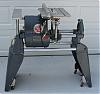
Shopsmith Motor Speed Control
Many years ago, I played with the idea that if the Shopsmith motor operated slower on the 50 cycle power. then why not make a power supply that would vary the frquency from 10 to 120 cycles for 110 VAC output. I got as far as building a proto-type and believed I may had started testing on a 3/4 HP Shopsmith motor. My memory failed me at that time and only recently, last 6 months, remembered what I was trying to do. I found a box of some of the parts that I was using that triggered my memory again. I was never able to find anyone who could tell me if I was only chasing a dream or what to expect when varing the frequency. I do remember testing the outut with test meters to check the output but do not remember if I ever put a load on the output. I was looking at a box for less than $100 to accomplish this task. This was an extension of my efforts to build an electrical lock system to stop the motor rotor immediately. I did destory a couple motors during this phase but felt the few microseconds needed to stop the rotor was still too much plus there was a lot of noise when I did it. I reused many of the same parts for the cycle convertor. I had some many projects that I never completed but that is life with Alzheimer.
Bill Mayo bill.mayo@verizon.net
Shopsmith owner since 73. Sell, repair and rebuild Shopsmith, Total Shop & Wood Master headstocks, SPTs, attachments, accessories and parts. US Navy 1955-1975 (FTCS/E-8)
Shopsmith owner since 73. Sell, repair and rebuild Shopsmith, Total Shop & Wood Master headstocks, SPTs, attachments, accessories and parts. US Navy 1955-1975 (FTCS/E-8)
-
JPG
- Platinum Member
- Posts: 35600
- Joined: Wed Dec 10, 2008 7:42 pm
- Location: Lexington, Ky (TAMECAT territory)
Unless the motor magnetic structure was designed with the larger frequency and rpm range in mind, it is doubtful varying the frequency would be sufficient to also deliver the torque needed. JMHObillmayo wrote:Many years ago, I played with the idea that if the Shopsmith motor operated slower on the 50 cycle power. then why not make a power supply that would vary the frquency from 10 to 120 cycles for 110 VAC output. I got as far as building a proto-type and believed I may had started testing on a 3/4 HP Shopsmith motor. My memory failed me at that time and only recently, last 6 months, remembered what I was trying to do. I found a box of some of the parts that I was using that triggered my memory again. I was never able to find anyone who could tell me if I was only chasing a dream or what to expect when varing the frequency. I do remember testing the outut with test meters to check the output but do not remember if I ever put a load on the output. I was looking at a box for less than $100 to accomplish this task. This was an extension of my efforts to build an electrical lock system to stop the motor rotor immediately. I did destory a couple motors during this phase but felt the few microseconds needed to stop the rotor was still too much plus there was a lot of noise when I did it. I reused many of the same parts for the cycle convertor. I had some many projects that I never completed but that is life with Alzheimer.
╔═══╗
╟JPG ╢
╚═══╝
Goldie(Bought New SN 377425)/4" jointer/6" beltsander/12" planer/stripsander/bandsaw/powerstation /Scroll saw/Jig saw /Craftsman 10" ras/Craftsman 6" thicknessplaner/ Dayton10"tablesaw(restoredfromneighborstrashpile)/ Mark VII restoration in 'progress'/ 10E[/size](SN E3779) restoration in progress, a 510 on the back burner and a growing pile of items to be eventually returned to useful life. - aka Red Grange
╟JPG ╢
╚═══╝
Goldie(Bought New SN 377425)/4" jointer/6" beltsander/12" planer/stripsander/bandsaw/powerstation /Scroll saw/Jig saw /Craftsman 10" ras/Craftsman 6" thicknessplaner/ Dayton10"tablesaw(restoredfromneighborstrashpile)/ Mark VII restoration in 'progress'/ 10E[/size](SN E3779) restoration in progress, a 510 on the back burner and a growing pile of items to be eventually returned to useful life. - aka Red Grange