GerikBensing
I'm rehabbing a Mark VII unit I purchased recently and one of the issues I found was that the idler shaft that holds the eccentric bearing had a lot of play in it. Disassembling it I found the shaft has worn away from where the bearing is supposed to ride.
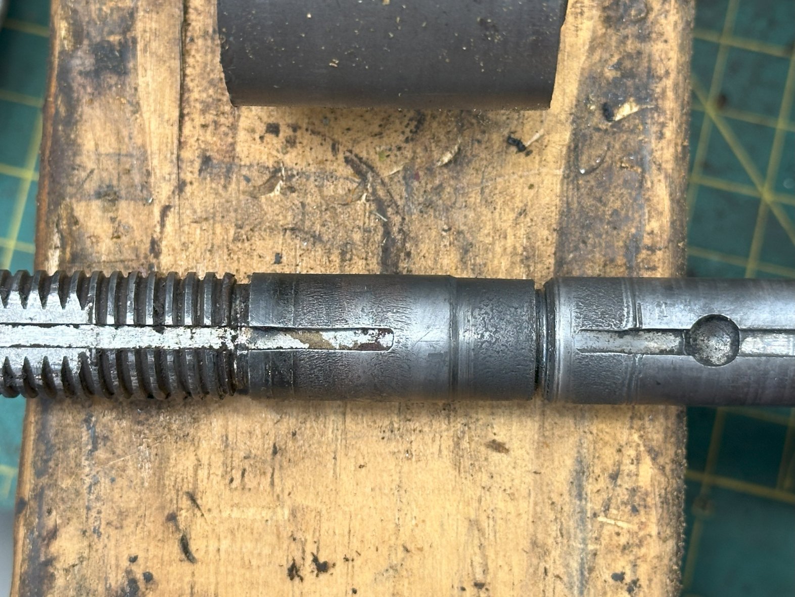
Does anyone have any advice on if there is a way to repair this? I've done some research and found there is an epoxy or special welding machine process for shaft repairs in general and put out some feelers locally if anyone offers such a service. Of course, the easiest thing to do would be to replace it but this is a Mark VII only part and I can't seem to find a replacement. It looks like a Mark V idler shaft is similar, but I don't believe it's similar enough from what I can tell.
I have a full video of my Shopsmith Mark VII teardown as well. Video showing this part wobbling is at 8:54.
Any advice would be appreciated!
[deleted]
I'm not a Mark VII guy, but since they haven't weighed in... There have been threads with similar problems. One member adapted a Mark 5/V speed control and in the other the resolution isn't clear:
https://forum.shopsmith.com/viewtopic.php?p=311335#p311335
https://forum.shopsmith.com/viewtopic.php?p=294730#p294730
While the Idlers are significantly different, it isn't obvious to me why a Mark 5/V Idler would not work. The obvious differences are in the attachment of bearing to shaft, but as long as the bearing and shaft fit together this isn't necessarily a problem. From my non-Mark VII perspective, adapting the entire M 5/V speed control seems good as it eliminates another known problem area, the speed control cam. Though I don't love the new style, the old style Mark 5/V Idlers and bearings are relatively bomb-proof.
There are multiple methods for metal deposition as you describe for a potential resolution, and also epoxy based solutions. I would think that finding a machine shop that can do this and rebuild the shaft should be okay, not necessarily inexpensive. Similarly a machine shop could make a new shaft, also perhaps a bit expensive. IIWM I'd want to definitively rule out using or adapting an old-style Mark V/5 shaft first because intuitively that seems easier and less expensive. I would guess that the Mark VII experts already know why that won't work.
Good luck!
- David
GerikBensing
Yeah, adapting it to a Mark V speed controller setup crossed my mind when I found that post. I'll have to pull the idler shaft out of my Mark V and see just how different they are.
It seems like a new (used) Mark VII idler shaft would be ideal but I've not found a source for one yet. If I had a metal lathe doing the fancy shaft repair epoxy would probably be pretty quick and easy, but alas I do not own one and don't know anyone who does.
miken
I have a lathe and a mill and would be happy to help, but I don't have any experience with an epoxy style fix. I would assume it would need to be turned down considerably in order to get a decent build up thickness, and probably would need to knurl it for epoxy adhesion? If it was my problem, I might try turning it down and press on a new sleeve. Then turn that to match the o.d. it should be. That would require rethreading the end to a smaller size. I cant remember if that keyway on the threaded end is needed under the eccentric? I'd probably give that a try first, and then just make a new one.
Spray welding is the fix for this, but I think the cost would be an issue.
Mike
[Edit] after thinking more about this, I would turn the worn area under the bearing to a specific o.d. then create a two piece split sleeve that you could assemble one piece on each side as you push the bearing into place. Like shimming under the bearing.
JPG
1) the MVII idler shaft bearing is entirely different from a M5/V but is similar to the new two bearing version now used on the M7..
2) The spacing of the MVII bearings is different.
3) The threaded portion of the MVII idler shaft only serves to accommodate the nut which provides a positional stop for the bearing 'assembly'.
4) The turn down/two part sleeve scheme would likely work for the excessivly worn location where one of the bearings was originally located.
5) A similar scheme would likely be needed where the second bearing was originally located.
6) An issue not mentioned is the wear to the edge of the snap ring groove that positions the inner bearing and limits the idler sheave travel towards the bearing.
7) I think a suitable replacement could be made from 5/8" shafting by someone with an engine lathe and and ability to add a 1/8" keyway and drill the key end hole/dimple and create the snap ring groove. A second groove could serve to limit the bearing assembly movement towards the shaft end thus eliminating the acme threaded end/nut/retainer. Lastly the flat for the coupling would need to be machined.
tomthank
This content is like a beacon of truth shining brightly.
miken
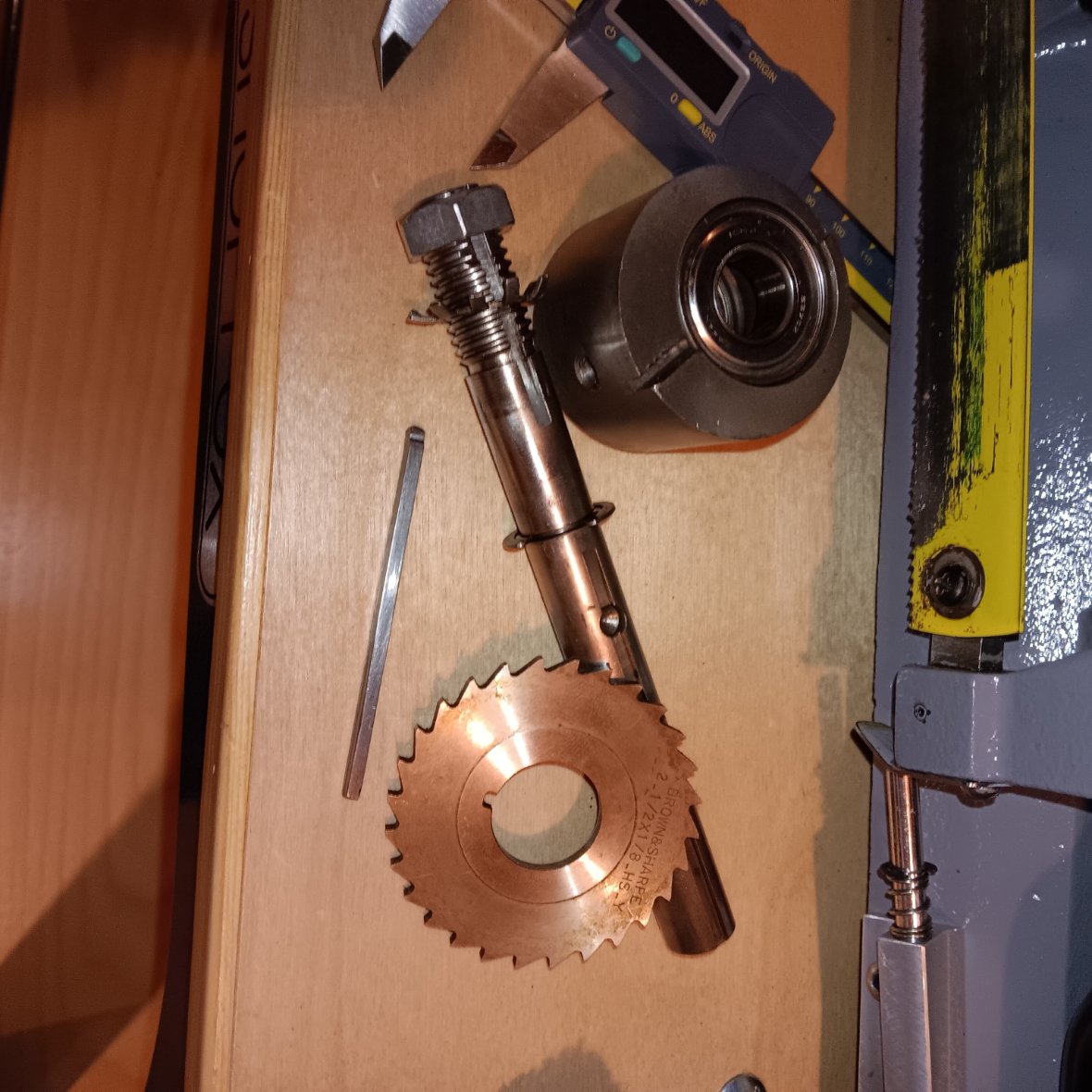
JPG, you are correct. I pulled my idler to have a better look. It would be far easier to just make a new one than deal with the tolerancing of a split sleeve and a fix for that eclip groove. I believe it is only a piece of 5/8" ground drill rod, and I just happen to have a 1/8" keyway cutter for the horizontal mill. The threads on the end don't need to be acme. I could single point cut a 5/8-11. I already have an eclip grooving tool I ground for another project.
GerikBensing
Miken, if you think it'd be easier to simply remake this shaft, I do think it's the better option. Sounds like you have the tools necessary to make this happen. I'll send you a PM.
JPG
My clumsy measurements are: O/D 5/8", LENGTH 6 3/8", INNER END TO KEY STOP DIMPLE CENTER 2 15/16", INNER END TO OUTER EDGE OF E-CLIP GROOVE 3 3/4", E-CLIP THICKNESS 0.050", OUTER END TO BEARING EDGE OF RETAINING E-CLIP 1 1/4", INTERNAL BEARING SPACER 1/2", BEARING THICKNESS(EACH) 11 mm.
The key slot need only be flat to the inner edge of the dimple.
I say clumsy because adding everything up is slightly greater than 6 3/8"(6.416). ***
A tapered flat on the outer end would be 'nice'.
*** Closer examination reveals the 6 3/8 length is actually longer by about 1/32. The critical dimension is the inner edges of the e-clip grooves must be no less than 1.367".
FWIW an 'extra' idler assembly I have appears to have a groove cut at the end of the threads that would provide the external e-clip as suggested above however it is shallow so I suspect it is a relief cut for the threads. Perfect location though. ???
miken
Good info JPG, they cut the keyway using a slitting saw or keyway cutter, thus the reason for the keyway going past the dimple hole. It does a better job than using an end mill. Yes, my two idler shafts do not have outer eclips and I suspect as you noted they are really intended to be thread relief. Correct me but I think the threads are acme because the Jointer coupling lug is driven from this. The flat top threads are less likely to be damaged (flattened) by the lug. I'd need to think if I can grind an accurate acme thread cutter. Maybe your double eclip, no threads idea is best?
JPG
Tis simpler for sure! Acme fer sure! I think the threads are tolerated rather than by design.(raw material source)
The outer end keyway is redundant and exists only for the nut locking whatchamacallit.
I really think the second(outer) retaining clip is better as long as bearing clearance is correct(>0 but small).
If ya make 'some' I would like one. :)
miken
Sure JPG, I can make you one. PM me.
Mike
GerikBensing
The threads seem skippable if you can retain everything like the Mark V does. Not sure what the secret is (if there is any). I'm in talks now with Mike to give this a go.
JPG
The threads serve NO shopsmith function.
kmilesone
I have the same problem with my Mark VII Idler shaft is scored under the rear bearing maybe 5 thousands and if you are looking to make some of these idler shafts I would be interested in one if possible.
miken
JPG is in the process of sending me some shaft material, 1045 stress proof I believe is what he sourced. Let me give it a try and see how it goes. It should be pretty easy to make the shaft using the double eclip method and no acme threading. I will post up some pics when I get into it.
Mike
GerikBensing
I need to order new bearings to go into the eccentric so I can send Mike the parts he needs and the ones in there now are KOYO S375Z bearings. These appear to be no longer made. Does anyone know a suitable substitution?
While I'm at it, I'm going to try and replace all my bearings because... why not?
I have a Federal 1205LL and KOYO 6205Z on the drive sleeve assembly
I have a FAFNIR 202KDD5 on the Spindle Assy (single bearing)
I have a 626Z on the Control Assembly Sleeve (the tiny one)
part numbers seem like they can get a little convoluted and couldn't find a definitely list of what's what when it comes to bearings. Can anyone point me in the right direction? I have a local Motion Industries (which someone said is a good resource for getting bearings) that I'll check out to see if they can source me good ones.
jsburger
Before you pull your hair out, check with Motion Industries. If nothing else take the bearing in to them so they can measure it and come up with an equivalent. Many (most) bearings are speced in metric even in the US.
JPG
Idler bearings 5/8" x 35mm x 11mm 6202-10-2RS
Drive Sleeve 25mm x 52mm x 15mm 6205 ZZ
I would retain the Fafnir if it is not damaged
Do not mess with the control sheave bearing unless it is damaged
kmilesone
For the idler shaft I ordered 202 kdd its the same bearing I removed 15mmx35mmx11mm double shielded right from Amazon $11.49 each
For the drive sleeve I ordered 6205-zz 25mmx52mmx15mm double shielded again right from Amazon $8.95 each
