
Hi,
As some of you may know I have a Shopsmith 10ER I just got. It is the first one I have seen up close and personal... touching and hefting as well. I will be giving this one to my brother as a birthday gift but if I EVER have space I'll get one for myself too.
I'm really having trouble not digging and and working on it but then part of the gift well be for him to do that so... But I did power it up to make sure it at least ran. I also decided to check the bearings. While they feel tight and I don't think they are damaged they also feel stiff like they are running in 58 year old grease. Not sure what I want to do about that. In the pictures you will see I have both the quill and pulley side bearings out. When I get it back together I might add a picture with them just for completeness.
This well be several posts due to the 5 limit of images per posting. I may not do them all today as it takes a while but I think some of you are going to find this very interesting in light of some discussions in the past.
So off we go with an image of the hole where the quill should be. As you can see it looks a lot like the current design as far as the gear system.
[ATTACH]3614[/ATTACH]
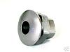
Next is the other end where the bearings set that are for the drive portion of the machine. A little later I have a picture of what the missing piece looks like but for now think of it as a pair of bearings with a pulley attached to a shaft.
[ATTACH]3615[/ATTACH]
Check out the tubes on this beauty... makes you want to go park a Buick on them. They look to be just short of a 1/4" tube thickness. This is the end that goes in the air when setting up in drill press mode, the tubes come though the tie bar and a threaded knob is used rather then the latch idea of the newer models.
[ATTACH]3616[/ATTACH]
Yes the pulley is the drive and yes it is exposed on the lower end. As you can see you need to move the belt from pulley to pulley to change speed. This was the stock setup but they had a speed changer you could add... this machine didn't have that option.
[ATTACH]3617[/ATTACH]
The lever is the quill lock. The quill spring I haven't had apart so I can't tell you how that works but in general it is about the same in function.
[ATTACH]3618[/ATTACH]
Ed
10ER in pictures, lite on the review
Moderator: admin
10ER in pictures, lite on the review
- Attachments
-
- P3220011sc.jpg (81.16 KiB) Viewed 6891 times
-
- P3220013sc.jpg (85.6 KiB) Viewed 6888 times
-
- P3220014sc.jpg (90.63 KiB) Viewed 6890 times
-
- P3220016sc.jpg (88.57 KiB) Viewed 6892 times
-
- P3220017sc.jpg (80.41 KiB) Viewed 6886 times
{Knight of the Shopsmith} [Hero's don't wear capes, they wear dog tags]
Hi,
Next you can see the headstock lock. I like the feel of the levers, the pictures don't let you feel them but they have a nice smooth flow to them.
[ATTACH]3619[/ATTACH]
This is the knob that holds the top pulley guard in place. This machine is missing that part but I really want to get one as soon as I can... it didn't worry me to much in this position but when in drill press mode it could be a hair pulling experience. And yes even in the horizontal mode it feels a little unsafe.
[ATTACH]3620[/ATTACH]
Just like on the current machines you can move the lever to either side.
[ATTACH]3621[/ATTACH]
Next we have the quill and the drive pulley assembly. Not much more I can say about them.
[ATTACH]3622[/ATTACH]
A little longer shot at the head stock. As you can see the motor mounts below and has a pair of tubes that are used to adjust the belt tension. To tight you wreak the bearings and too loose and the belt hits the tubes. Yes the belt goes between the tubes so you are limit as to the size of pulley's you can use.
[ATTACH]3623[/ATTACH]
Ed
- Attachments
-
- P3220018sc.jpg (87.43 KiB) Viewed 6878 times
-
- P3220019sc.jpg (79 KiB) Viewed 6880 times
-
- P3220020sc.jpg (82.95 KiB) Viewed 6879 times
-
- P3220021sc.jpg (76.38 KiB) Viewed 6879 times
-
- P3220022sc.jpg (125.34 KiB) Viewed 6875 times
{Knight of the Shopsmith} [Hero's don't wear capes, they wear dog tags]
Hi, are you still here?
Please note the crank under the carriage, you will see more of that and what it is for a bit later.
[ATTACH]3629[/ATTACH]
Notice the pivot point and how they have the off set. You can also see the knob for locking it in that position.
[ATTACH]3630[/ATTACH]
This a good shot showing the carriage lock and the table height locks, and a better view of the drill press lock position lock.
[ATTACH]3631[/ATTACH]
Here is a shot giving more of a prospective from the end.
[ATTACH]3632[/ATTACH]
Take a look at the cord, mice or from the exposed pulley... up and it person you can tell it was from the pulley. That could make a mess of a pulley and anyone near the shower of metal... could even cause a fire with all the sawdust around.
[ATTACH]3633[/ATTACH]
Still more to come.
Ed
- Attachments
-
- P3220023sca.jpg (90.23 KiB) Viewed 6862 times
-
- P3220024sc.jpg (109.02 KiB) Viewed 6882 times
-
- P3220025sc.jpg (96.42 KiB) Viewed 6866 times
-
- P3220026rsc.jpg (80.14 KiB) Viewed 6870 times
-
- P3220027sc.jpg (71.55 KiB) Viewed 6864 times
{Knight of the Shopsmith} [Hero's don't wear capes, they wear dog tags]
Hey who needs a ground when you can have a homemade chipboard piece on your power cord??? Original??
[ATTACH]3634[/ATTACH]
The next collection is of the main table. Take a look at how some of the stuff was done back then, especially the 90 and 45 degree lock positions.
[ATTACH]3635[/ATTACH]
[ATTACH]3636[/ATTACH]
[ATTACH]3637[/ATTACH]
Another picture of the crank, this time from above. Also note the part of the height adjuster in the last couple of pictures.
[ATTACH]3638[/ATTACH]
Wonder what will be in the next batch of picture in the next post???
Ed
- Attachments
-
- P3220030sc.jpg (73.54 KiB) Viewed 6857 times
-
- P3220031sc.jpg (92.5 KiB) Viewed 6960 times
-
- P3220032sc.jpg (69.03 KiB) Viewed 6950 times
-
- P3220033sc.jpg (74.28 KiB) Viewed 6869 times
-
- P3220034sc.jpg (112.4 KiB) Viewed 6853 times
{Knight of the Shopsmith} [Hero's don't wear capes, they wear dog tags]
What is up next is how the crank and the top all come together. Interesting design hey?
[ATTACH]3639[/ATTACH]
The miter gauge. A bit different then today's but interesting all the same.
[ATTACH]3640[/ATTACH]
The next time is the extension table of that day. First a couple shots of it from the sides and then a shot of it mounted on the machine.
[ATTACH]3641[/ATTACH]
[ATTACH]3642[/ATTACH]
[ATTACH]3643[/ATTACH]
Ed
- Attachments
-
- P3220035sc.jpg (117.56 KiB) Viewed 6860 times
-
- P3220038asc.jpg (82.6 KiB) Viewed 6873 times
-
- P3220042c.jpg (51.37 KiB) Viewed 6853 times
-
- P3220043c.jpg (52.33 KiB) Viewed 6847 times
-
- P3220044sc.jpg (99.5 KiB) Viewed 6846 times
{Knight of the Shopsmith} [Hero's don't wear capes, they wear dog tags]
We are getting near then end...
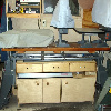
Another view showing the main table and extension table. Almost looks like a shopsmith doesn't it?
[ATTACH]3644[/ATTACH]
The saw guard. As I understand it they never did make a bottom part for it. This one I don't think got much use.
[ATTACH]3645[/ATTACH]
The 12 sanding disk and a smaller one, I think it is 8" but I never did measure it to be sure. I think the smaller one is from shopsmith but I am really not sure as the design is very different.
[ATTACH]3646[/ATTACH]
And to round out this post the lathe tool rest.
[ATTACH]3647[/ATTACH]
Now for a shocking revelation check the next posting.
- Attachments
-
- P3220045sc.jpg (115.11 KiB) Viewed 6897 times
-
- P3220047asc.jpg (90.5 KiB) Viewed 6852 times
-
- P3220049sc.jpg (83.58 KiB) Viewed 6873 times
-
- P3220050sc.jpg (100.06 KiB) Viewed 6855 times
{Knight of the Shopsmith} [Hero's don't wear capes, they wear dog tags]
-
easterngray
- Platinum Member
- Posts: 720
- Joined: Sun Mar 11, 2007 8:28 pm
- Location: Cape Cod MA.
-
kartoffelkopf

- Gold Member
- Posts: 35
- Joined: Sun Dec 07, 2008 4:42 pm
- Location: central IL
Sorry, they are not.easterngray wrote:Thanks Ed - Thats the most in depth look I've had at one of those machines. Can you confirm that the tube dimensions are the same as the Mark V tubes? I would love to have heavier bench tubes on my Goldie. Thanks again. Alec
Kartoffelkopf… because no one expects much from a potato head.
SS 520, Power Station, scroll saw, Pro Planer, DeWalt 746 Table Saw w/ Jointech cabinet maker's system, Jet JJ6CSX jointer, Jet 22-44 Closed Base Drum Sander, Grizzly G0513P Bandsaw, Powermatic PM1300 Dust Collector
SS 520, Power Station, scroll saw, Pro Planer, DeWalt 746 Table Saw w/ Jointech cabinet maker's system, Jet JJ6CSX jointer, Jet 22-44 Closed Base Drum Sander, Grizzly G0513P Bandsaw, Powermatic PM1300 Dust Collector
Dare I even post this?
Please read at your own risk.
This post has to deal with the miter slot... those that want to remain clueless please do not read.
Warning this may be a spoiler!
OK you have been warned. What would you say if I told you my current miter gauge bar doesn't fit the old machine? What if I told you it is too tall and is VERY sloppy width wise? What if I said the old miter bar is to wide to fit in the 520 table?
So here is a picture of the loose fit of the bar in the old table.
[ATTACH]3652[/ATTACH]
Check to see how high it sets.
[ATTACH]3653[/ATTACH]
Now the old bar trying to fit the new table.
[ATTACH]3654[/ATTACH]
Old bar checking in at just under .750"
[ATTACH]3655[/ATTACH]
Height of old bar at about .250"
[ATTACH]3656[/ATTACH]
OK slow your breathing down and take a little deep breath... you will be OK.
Of course it could be that someone has altered this machine so until someone else can check this out you can still think what you will about the great controversy of the miter bar.
Ed
- Attachments
-
- P3220039asc.jpg (85.91 KiB) Viewed 6844 times
-
- P3220040asc.jpg (54.52 KiB) Viewed 6843 times
-
- P3220041asc.jpg (53.91 KiB) Viewed 6846 times
-
- P3220051asc.jpg (65.63 KiB) Viewed 6843 times
-
- P3220052asc.jpg (70.88 KiB) Viewed 6840 times
{Knight of the Shopsmith} [Hero's don't wear capes, they wear dog tags]
So Ed,
By now you have realized that the old antique has a 3/4" wide miter slot, albeit shallower than the standard 3/8". If you dug far enough into the quill you might have found two bearings.And, how about the incremental height adjustment on the table with that crank. The 10ER offers some very nice qualities and offers some fine genes for its offspring.
Are you sure you don't want to find another one to give as a gift?
Rob in San Diego
Email: SDSSmith51 AT gmail.com
Email: SDSSmith51 AT gmail.com