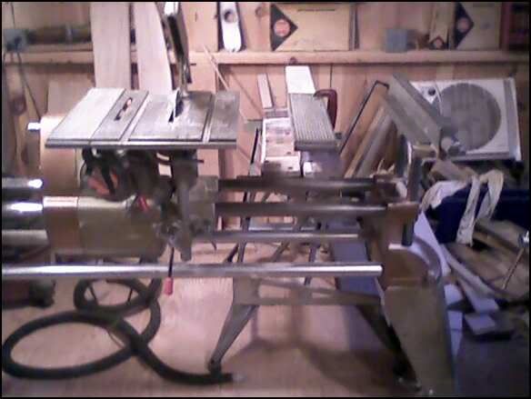
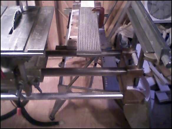
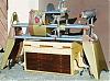
I have several extra extension table surfaces. I was thinking that I might be able to make use of them by fabricating a home made 510/520 style table and floating table. Here's a picture of the 500 with an extra table clamped to the left edge of the main table - As long as you're accurate with your drilling, this should be a simple mod and will add consideably to the left side of the main table. To the right of the headstock is an extension table positioned as if it was a floating table. I think the only way to do this is to run small diameter solid steel bars throught the tables side edges, about two or three inches in from the front and rear edges, and attach a locking knob on the bottom of all three tables. If there were holes drilled through both edges of the extension table the bars could be inserted through the extension table, then through the floating table and the right main table edge and locked in place. The floating table could then be positioned as needed and locked as well. A couple of adjustable stop collars would insure that the main table and extension table are flush.
Obviously the real clincher for this kind of mod is getting the holes for the bars drilled dead on and having them of sufficient diameter for strength, yet not to destroy the rigidity of the extension and floating table structure.
Perhaps a rail system that attached to the bottom of the tables would be better?
Am I overlooking anything that makes this unreasonable? Any feedback is welcome - thanks, Alec
1960 Aniversary Model Mark 5 500 "Goldie" with most SPT's
I am not certain that I have a good mental picture of what needs to be done. Several past discussions regarding the earlier models has taught me that the Shopsmiths are not all alike.
However, if I had this task (as I understand it) to do, I would use a piece of flat iron to make drill templates. By locating all holes with use of that template it should be rather simple (after the template is positioned, clamped and rechecked).
A second thought:
Could two floating tables be converted into one by using something like J-B Weld.
"Making Sawdust Safely" Dusty
Sent from my Dell XPS using Firefox.
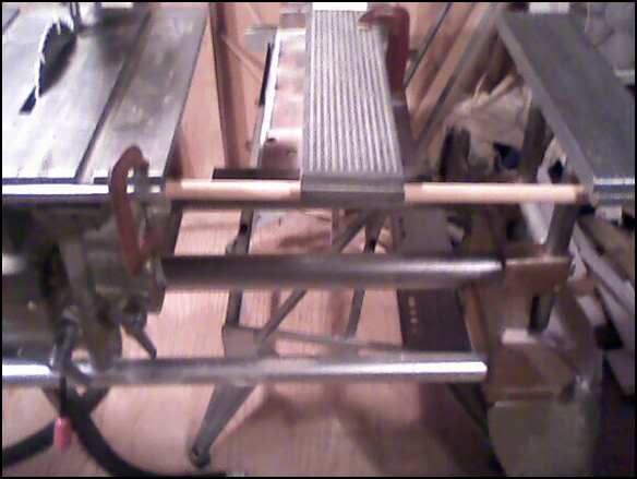
Would that bear a lot of weight? could you use dowels like in the pic, or would there be way too much flex? I'm thinking any wood that you're cutting would be supported by the main and support tables on either end and the floating table would still be able to support the weight without flex.
What if you used something, like say a U-Bolt that you can slide the dowel into and then tighten. Maybe weld U- bolts to the bottom of the table some how ( I wouldn't have the smallest clue if its possible).
A floating table would sure be nice for very large flexible stock like formica or bendable laminated wood. I always thought about using another sliding table on a seperate carriage for that purpose. Lots of reasons why I never did that but the top one for me was having 1 more surface to adjust to the same plane. I think the 520 retrofit kit is the best option, even considering the cost.
That's just my .02$ worth. Happy New Year everyone!!
My initial thoughts are to make metal brackets to mount to the sides of the main, extension and 'floating table'. A couple of screw holes and a large hole for the connecting 'tube'. These brackets would need to be precisely located on the front of end of all tables and referenced to both the top surface and the miter gauge rail. The rear is a little crowded on the main table due to the nearness of the trunion bracket to the back edge. Also there is not as much side flange surface in the rear.
This would allow 'aligning them', but does not address the need to clamp the 'connecting tube'. Also the brackets on the sides of the tables, prevents a flush fit between them(unless they are mounted on the inside of the table[requires c'sunk. screw in thin alum ]).
If the brackets were thick enough, a lock screw/knob could be threaded into the bottom edge of the brackets.
╔═══╗
╟JPG ╢
╚═══╝
Goldie(Bought New SN 377425)/4" jointer/6" beltsander/12" planer/stripsander/bandsaw/powerstation /Scroll saw/Jig saw /Craftsman 10" ras/Craftsman 6" thicknessplaner/ Dayton10"tablesaw(restoredfromneighborstrashpile)/ Mark VII restoration in 'progress'/ 10E[/size](SN E3779) restoration in progress, a 510 on the back burner and a growing pile of items to be eventually returned to useful life. - aka Red Grange
rather than precision drill a bunch of holes, why not just mount them to a stand sitting on the way tubes?
you could make a couple of feet that clamp to the way tubes and use the height adjustment from the roller stand in the PTWFE book. someone posted a picture of theirs recently, but I cannot find that thread now.
just a thought.
Ivan
Mark V (84) w/ jigsaw, belt sander, strip sander
ER10 awaiting restoration
"Small diameter solid steel bars" of a given length will still have flex. If long enough to be used in the first picture in the thread to hold the middle table, the weight of the "floating" extension table might cause enough flex so that it might not line up with the others on the same plane.
That was definiltely a concern of mine Mike. Looks like a real 520 upgrade is the only reasonable solution. Too high a cost for me right now though... Thanks guys - Alec
1960 Aniversary Model Mark 5 500 "Goldie" with most SPT's
Enjoy seeing the copper and gold Shopsmith... This plus the very original vertical tool storage beneficially apply to all Shopsmith models. Thanks for the pictures and efforts.
Can the auxilary table be extended from the main table to allow cutting of long - bevels on stock that is wider than permitted by fence placement on the main table, (a bevel on a 2' L by 12" W stock)? This is done on the 520 by extending a floating table over the end wih a fence on the floating table.
MK V 520; MK V 510 w/PP DIY Upgrade; MK 5 500; Jointer; Bandsaw; Sliding Table; Conical Sanding Disk; Sharpening Guide, Lathe Duplicator, Jigsaw, Scrollsaw, Beltsander, Ring Master, Biscuit Joiner.
I had a similar idea as I had several extra extension table tops as well. The sides are not exactly perpendicular to the top so I machined them so when I bolted them together the tops were flat. It worked great for an extra wide extension table and would probably work to increase the size of the main table also. I think I would put it on the right side so that the left side bevel on the main saw table would still be available for disc sanding at angles. I haven't thought much about floating table idea. Here is what I did with them. http://mkctools.com/mvdoubleext.htm
Skip Campbell
easterngray wrote:I have several extra extension table surfaces. I was thinking that I might be able to make use of them by fabricating a home made 510/520 style table and floating table. Here's a picture of the 500 with an extra table clamped to the left edge of the main table - As long as you're accurate with your drilling, this should be a simple mod and will add consideably to the left side of the main table. To the right of the headstock is an extension table positioned as if it was a floating table. I think the only way to do this is to run small diameter solid steel bars throught the tables side edges, about two or three inches in from the front and rear edges, and attach a locking knob on the bottom of all three tables. If there were holes drilled through both edges of the extension table the bars could be inserted through the extension table, then through the floating table and the right main table edge and locked in place. The floating table could then be positioned as needed and locked as well. A couple of adjustable stop collars would insure that the main table and extension table are flush.
Obviously the real clincher for this kind of mod is getting the holes for the bars drilled dead on and having them of sufficient diameter for strength, yet not to destroy the rigidity of the extension and floating table structure.
Perhaps a rail system that attached to the bottom of the tables would be better?
Am I overlooking anything that makes this unreasonable? Any feedback is welcome - thanks, Alec