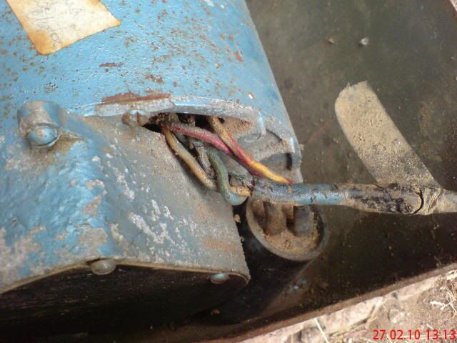
dusty wrote:Looking at your photos, it appears that the capacitor is connected to a red wire and a yellow with red tracer wire. I also see those two wires coming out of the motor. I think those two are definite.
Correct - at the capacitor the wires are red and yellow with red stripe

But they both look red going into the stator - probably brcause of previous overheating.

dusty wrote:Coming out of the cord (with burned outer insulation) I think I see three wires. This is also what I would suspect one appears to be green, one is white or slate and the third is hard to tell but I would bet it is black.
Actually, the green wire you see has nothing to do with the power into the motor - It connects Stator windings, and is just wound in the insulation tape to tidy up the excess. The earth wire (ground) you expected to see is long gone.
The power cable coming into the motor is just a black & a white.

dusty wrote:If I am correct so far AND you are wiring this for 110 vac, this is a dead cinch. ... ...
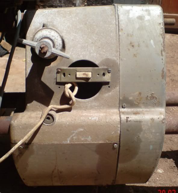
In some applications both the white (neutral) and the black (hot) get routed through switches usually housed in the same casing (this is a DPST switch).
I will be installing a DPST switch, but this will be a 220/240 V power supply.
dusty wrote:Do you know that this motor worked before you did the tear down?
It definitely did not work. In hindsight it looks like I was stupid to try putting power onto this motor, but it is so bad that it couldn't even short out.

More to come in my next post - too bad we're limited to 4 graphics per entry.
.