
Hello all,
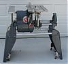
Has anyone seen a motor with an external "motor starting switch" mounted on the motor case next to the starting capacitor? See attached photo.
I have been having intermittent starting issues.
The motor bearings have been replaced and the capacitor is new.
It looks like the starting switch is sealed. So I don't think it has sawdust in it.
This Shopsmith Mark VII came from my father in the mid-1960s. He purchased it from a hardware store in Cadillac, Michigan.
Thanks
[ATTACH]11313[/ATTACH]
Mark VII motor starting switch (not inside the motor)
Moderator: admin
Mark VII motor starting switch (not inside the motor)
- Attachments
-
- SS_Mot_Strt_Sw_002.JPG (73.47 KiB) Viewed 6674 times
-
JPG

- Platinum Member
- Posts: 35600
- Joined: Wed Dec 10, 2008 7:42 pm
- Location: Lexington, Ky (TAMECAT territory)
It appears to me that you have a capacitive run/inductive start motor. That box is a 'start' relay. It switches the 'start' winding out when the motor gets up and going. It senses the current and connects the start winding when the run winding current is high(when starting).
Then again, I be guessing only from the pix.
Then again, I be guessing only from the pix.
╔═══╗
╟JPG ╢
╚═══╝
Goldie(Bought New SN 377425)/4" jointer/6" beltsander/12" planer/stripsander/bandsaw/powerstation /Scroll saw/Jig saw /Craftsman 10" ras/Craftsman 6" thicknessplaner/ Dayton10"tablesaw(restoredfromneighborstrashpile)/ Mark VII restoration in 'progress'/ 10E[/size](SN E3779) restoration in progress, a 510 on the back burner and a growing pile of items to be eventually returned to useful life. - aka Red Grange
I have purchased several MK VII motors without any external relay/box. I have been using a ON/OFF switch (2 wires) and a DPDT switch (4 wires) for the FWD/REV of the motor in place of the pushbuttons.
My first guess would be a relay box to switch from forward to reverse motor rotation. Any information from the relay/box would be helpful. Does your MK VII have a separate forward, off and reverse pushbutton? The color of each motor wire would be helpful as several different MK VII motors was used.
If not a FWD/REV switch, then the box could be a Current Relay (Relay: 3ARR3 MARS550 is a replacement used on early 3/4 HP motors) that was used in place of a centrifugal rotor mounted weights and a centrifugal switch points on a circuit board for the start windings. However, I am unaware of this relay type being used on the MK VII motors.
I have MK VII motor wiring diagrams and information available.
Bill Mayo bill.mayo@verizon.net
Shopsmith owner since 73. Sell, repair and rebuild Shopsmith, Total Shop & Wood Master headstocks, SPTs, attachments, accessories and parts. US Navy 1955-1975 (FTCS/E-8)
Shopsmith owner since 73. Sell, repair and rebuild Shopsmith, Total Shop & Wood Master headstocks, SPTs, attachments, accessories and parts. US Navy 1955-1975 (FTCS/E-8)
Thanks for the quick reply,
I've found the link below from the information you had given:
https://forum.shopsmith.com/viewtopic.php?t=3227
I'm trying to understand how the "black box" works.
Attached are (1) the wiring diagram from my Mark VII original documentation and (2) the markings on the "black box", and (3) my guess at the schematic for the "black box" - starting capacitor - motor.
Any ideas of how this might work?
[ATTACH]11329[/ATTACH]
[ATTACH]11330[/ATTACH]
[ATTACH]11331[/ATTACH]
- Attachments
-
- Motor_Schematic.JPG (60.47 KiB) Viewed 6845 times
-
- SS_Mot_Strt_Sw_003.JPG (39.87 KiB) Viewed 6664 times
-
- Potential_Relay_Schematic_2sma.JPG (37.51 KiB) Viewed 6705 times
~Ryan
-
JPG
- Platinum Member
- Posts: 35600
- Joined: Wed Dec 10, 2008 7:42 pm
- Location: Lexington, Ky (TAMECAT territory)
ryansm7 wrote:Thanks for the quick reply,
I've found the link below from the information you had given:
https://forum.shopsmith.com/viewtopic.php?t=3227
I'm trying to understand how the "black box" works.
Attached are (1) the wiring diagram from my Mark VII original documentation and (2) the markings on the "black box", and (3) my guess at the schematic for the "black box" - starting capacitor - motor.
Any ideas of how this might work?
[ATTACH]11329[/ATTACH]
[ATTACH]11330[/ATTACH]
[ATTACH]11331[/ATTACH]
Understand the switching action will help!
https://forum.shopsmith.com/viewtopic.php?p=29656&postcount=12
The L1/L2 terminals turn the motor on when either fwd or reverse.(wh/bk)
The T5/T9/5/2 terminals merely reverse the red/red-tracer wiring to the relay/cap/motor wires(notice the 'no2', 'no5' labeling of the relay wiring coming from the switch).
The 'no2' is connected to the start relay to one side of the current coil.
The 'no5' is connected to the start relay start winding connection(other end of coil) (yellow)
The start relay "1" terminal connected to the start cap is thus connected to either the red or the red tracer wires. That reversal of red , red tracer wire/cap polarity determines rotation direction.[the motor will run either direction if manually started][the coils are thus 'ambidextrous!]
Not sure your start relay schematic is accurate(S/R reversed????)
BTW it is an Inductive run, Capacitive start motor(I stand corrected-the start relay through me off-shoulda known better!!!)
╔═══╗
╟JPG ╢
╚═══╝
Goldie(Bought New SN 377425)/4" jointer/6" beltsander/12" planer/stripsander/bandsaw/powerstation /Scroll saw/Jig saw /Craftsman 10" ras/Craftsman 6" thicknessplaner/ Dayton10"tablesaw(restoredfromneighborstrashpile)/ Mark VII restoration in 'progress'/ 10E[/size](SN E3779) restoration in progress, a 510 on the back burner and a growing pile of items to be eventually returned to useful life. - aka Red Grange
╟JPG ╢
╚═══╝
Goldie(Bought New SN 377425)/4" jointer/6" beltsander/12" planer/stripsander/bandsaw/powerstation /Scroll saw/Jig saw /Craftsman 10" ras/Craftsman 6" thicknessplaner/ Dayton10"tablesaw(restoredfromneighborstrashpile)/ Mark VII restoration in 'progress'/ 10E[/size](SN E3779) restoration in progress, a 510 on the back burner and a growing pile of items to be eventually returned to useful life. - aka Red Grange
JPG... you da man!!!
I'll check the connections on the Start/Run windings. If you are right about the capacitor polarity, I need to check the rotation direction on power-up.
I think the contacts of the relay should be normally closed at power-off (internal pins 1 to 2). I'll double check that also. Right now the diagram shows it normally open.
~Ryan
-
JPG
- Platinum Member
- Posts: 35600
- Joined: Wed Dec 10, 2008 7:42 pm
- Location: Lexington, Ky (TAMECAT territory)
ryansm7 wrote:JPG... you da man!!!
I'll check the connections on the Start/Run windings. If you are right about the capacitor polarity, I need to check the rotation direction on power-up.
I think the contacts of the relay should be normally closed at power-off (internal pins 1 to 2). I'll double check that also. Right now the diagram shows it normally open.
The contact should be normally open. The high run current at startup flowing through the coil causes the contacts to make thus connecting the start capacitor. After it gets up to speed, the run current decreases and the contacts again open taking the start capacitor and start winding out of action.
Two things to keep in mind.
The RUN winding current energizes the coil.
The start capacitor is switched 'on' by the high run current at slow speed and is disconnected when the run current drops below a starting level.
╔═══╗
╟JPG ╢
╚═══╝
Goldie(Bought New SN 377425)/4" jointer/6" beltsander/12" planer/stripsander/bandsaw/powerstation /Scroll saw/Jig saw /Craftsman 10" ras/Craftsman 6" thicknessplaner/ Dayton10"tablesaw(restoredfromneighborstrashpile)/ Mark VII restoration in 'progress'/ 10E[/size](SN E3779) restoration in progress, a 510 on the back burner and a growing pile of items to be eventually returned to useful life. - aka Red Grange
╟JPG ╢
╚═══╝
Goldie(Bought New SN 377425)/4" jointer/6" beltsander/12" planer/stripsander/bandsaw/powerstation /Scroll saw/Jig saw /Craftsman 10" ras/Craftsman 6" thicknessplaner/ Dayton10"tablesaw(restoredfromneighborstrashpile)/ Mark VII restoration in 'progress'/ 10E[/size](SN E3779) restoration in progress, a 510 on the back burner and a growing pile of items to be eventually returned to useful life. - aka Red Grange
Thanks again JPG,
I haven't pulled the motor out yet to make measurements on the relay. I guess I'd better just replace it before I run into permanent problems.
Do you think the MARS 550 would be a suitable substitute?
See attached spec.
[ATTACH]11338[/ATTACH]
I haven't pulled the motor out yet to make measurements on the relay. I guess I'd better just replace it before I run into permanent problems.
Do you think the MARS 550 would be a suitable substitute?
See attached spec.
[ATTACH]11338[/ATTACH]
- Attachments
-
- GE_Potential_Relay_Mars_550_551_3.JPG (42.77 KiB) Viewed 6704 times
~Ryan
-
JPG
- Platinum Member
- Posts: 35600
- Joined: Wed Dec 10, 2008 7:42 pm
- Location: Lexington, Ky (TAMECAT territory)
Maybe! How about a pix of the motor name plate!!!!!!ryansm7 wrote:Thanks again JPG,
I haven't pulled the motor out yet to make measurements on the relay. I guess I'd better just replace it before I run into permanent problems.
Do you think the MARS 550 would be a suitable substitute?
See attached spec.
[ATTACH]11338[/ATTACH]
╔═══╗
╟JPG ╢
╚═══╝
Goldie(Bought New SN 377425)/4" jointer/6" beltsander/12" planer/stripsander/bandsaw/powerstation /Scroll saw/Jig saw /Craftsman 10" ras/Craftsman 6" thicknessplaner/ Dayton10"tablesaw(restoredfromneighborstrashpile)/ Mark VII restoration in 'progress'/ 10E[/size](SN E3779) restoration in progress, a 510 on the back burner and a growing pile of items to be eventually returned to useful life. - aka Red Grange
╟JPG ╢
╚═══╝
Goldie(Bought New SN 377425)/4" jointer/6" beltsander/12" planer/stripsander/bandsaw/powerstation /Scroll saw/Jig saw /Craftsman 10" ras/Craftsman 6" thicknessplaner/ Dayton10"tablesaw(restoredfromneighborstrashpile)/ Mark VII restoration in 'progress'/ 10E[/size](SN E3779) restoration in progress, a 510 on the back burner and a growing pile of items to be eventually returned to useful life. - aka Red Grange
Hi JPG,
I could not get a clear pic of the motor name plate without completely removing the motor. Here are the specs for the motor. The following is exactly stamped into the name plate.
MODEL C48L2A7
HP 1-1/8
RPM 3450
CY 60
PH 1
SF 1.0
VOLTS 115
AMPS 12.6
SF AMPS
CODE H
TYPE CS
SER 163
FR 48
RISE 50
CONT DUTY
All measurements were taken with a digital multi-meter.
POWER ON MEASUREMENTS:
Pins 1 to 5.... 122VAC
Pins 1 to 2.... 300VAC
Pins 5 to 2.... 266VAC
POWER OFF MEASUREMENTS:
Pins 1 to 5.... 0VAC
Pins 1 to 2.... 0VAC
Pins 5 to 2.... 0VAC
The relay was electrically disconnected from the motor and capacitor for these measurements.
POWER OFF MEASUREMENTS:
Pins 1 to 5.... 3.2 Ohms
Pins 1 to 2.... 0.0 Ohms
Pins 5 to 2.... 3.2 Ohms
~Ryan