Page 3 of 6

Re: New member, not sure where to start.

Posted: Tue Dec 01, 2020 8:33 pm
by miken
Yes, I understand and any help will be appreciated. I did think about the possibility of accidentally passing by the off position while the motor was still running. I am not set on that switch, it was just one that I found and thought it looked like it had potential. It may actually be better to get the 8 terminal and use it for direction, and use an in-line corded switch or a separate DPST. Like I said, I haven't really put much thought into it. The original switch is currently working well enough to switch direction, just not start/stop.

Mike -

Re: New member, not sure where to start.

Posted: Fri Dec 04, 2020 10:18 pm
by miken
Ok, its back together and running great forward and reverse using the original switch, except for power wires. Can hear the centrifugal switch clicking off when powering down. Going to put the motor back into the headstock this weekend, then start thinking about the switch. The shrink tubing worked very well, and I appreciate the suggestion. One wire was too badly corroded so I clipped it back and soldered on a new wire. It wasn't as scary as i originally thought, watched some YouTube videos of people rewinding motors and realized that they aren't that fragile. Just need to be careful.
Thanks again, Mike

Re: New member, not sure where to start.

Posted: Fri Dec 04, 2020 10:36 pm
by JPG
One thing to consider re the taiss switch is size and where to mount it. I am sure the 12 contact version is 'longer' than the 8 contact version.

Re: New member, not sure where to start.

Posted: Sat Dec 05, 2020 1:08 pm
by rpd
This may be of interest. just the other day a member of the facebook group posted that he is working on a replacement switch for the old Mark VII.
link to post
https://www.facebook.com/groups/6844615 ... 4115593685

And for those who don't do facebook, I will quote it here.
Brandon Ausmus
December 3 at 8:38 PM ·
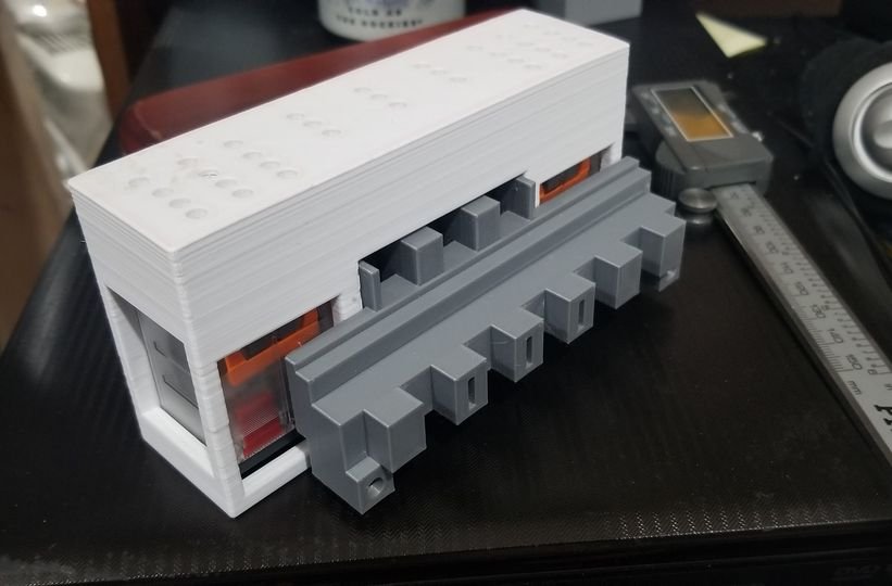
This is the current prototype for 3D printed replacement ShopSmith Mark VII switch that I've been working on during 2020. This prototype is ready for wiring and it's first fitment test. However, it's still missing a few key components, like the lights for the buttons.
This design includes modern safety features like auto reset if the power goes out, a snubber network to protect the switch from voltage spikes (which is what kills the original switch), A WARRANTY, and will be completely user serviceable!
The original goal was to keep it around the same price as a used one on Ebay (~$100), but that might not be possible. I think the price point will likely be closer to $150. Theres still some robust testing and final validation/verification to do, but when it's ready, I'll be making 20 of them during a low-rate initial production.
I don't expect them to fly off the shelves, but I intend to keep a handful in stock for anyone that needs one.
(It will be available in black, I'm just using cheap filament and low printing resolution for prototyping)
Additionally, if you own a Mark VII with an original working switch, I'll also be selling a snubber network addon to help protect it from further arc fouling.
I'd love some constructive comments and questions! 🙂
129965992_10109241589796793_2543863705880656853_o.jpg
129965992_10109241589796793_2543863705880656853_o.jpg (51.2 KiB) Viewed 2004 times
Mike King
It's not constructive, but it looks like it's made from LEGOS. But bravo for reverse engineering this beast.
2

· Reply
· 1d

Brandon Ausmus
Mike King
it's probably the holes on top that give it that vibe. The wiring goes through them to wire up the relays and switches. Once that's done it'll probably look more like Predator, lol.
1

· Reply
· 1d

Write a reply…

Greg Kruske
You are a wizard. Keep the updates coming...I’ll be in line for one of these
3

· Reply
· 1d

Daniel Taylor
Waycool! I bought a VII last year for $100 but was missing the tables and other stuff. I modified 500 table to fit VII carriage and slotted a 500 carriage to clear gear track to be able to mount a table to left of headstock. Headstock originally hummed… See More

· Reply
· 1d

Brandon Ausmus
Daniel Taylor
I do post in the forums sometimes, but I'm much more active on here. When it's closer to being finalized, I'll start a thread over there, too.

· Reply
· 1d

Write a reply…

Geoffrey Baker
badge icon
Very cool. But I hate to tell you, you've made it too large 🙂. But when you scale it down I'm sure people will pay over $100 for a new, working, improved switch!
How about designing a new plug in replacement for the main circuit board for the variable… See More
1

· Reply
· 1d · Edited

Brandon Ausmus
Geoffrey Baker
I believe it isn't too large. There should be enough clearance between it, the way tube, and the motor, but I won't know for certain until I get my headstock pulled apart and I get it installed, which is the next step.

· Reply
· 1d

Geoffrey Baker
badge icon
Brandon Ausmus
I was just kidding. It just looks huge in the perspective of the photo.
1

· Reply
· 1d

Brandon Ausmus
Geoffrey Baker
ah! I see what you mean. Yes, it does!
Here's it next to my Mark V for scale. 😅
Image may contain: indoor
8

· Reply
· 1d

Geoffrey Baker
badge icon
Too big... 🙂
1

· Reply
· 1d

Brandon Ausmus
Geoffrey Baker
do you have a part number for that circuit board you mentioned? I might take a stab at it next.

· Reply
· 21h

Geoffrey Baker
badge icon
Brandon Ausmus
the best I can do is give you this, which is a diagram of the full circuit. If you look closely you will see a dotted line, that represents the section of the circuit that is built onto the board.
No photo description available.

· Reply
· 21h · Edited


Steven Pool
Looks great! Looking forward to hearing more about the snubber thing for a working switch too. Keep up the good work!
1

· Reply
· 1d

John Valleau
Following. This is for the original Mk VII?
Got mine from my dad. He replaced it with a toggle switch for power and a DPDT switch for reverse.

· Reply
· 23h

Brandon Ausmus
John Valleau
yeah, this is for the original (1960s) Mark VII. I had replaced mine, too, with the intention of making this.

· Reply
· 23h

James Kabler Sr.
badge icon
I would be interested in the snubber.
1

· Reply
· 20h

Brandon Ausmus
James Kabler Sr.
I'll keep the group updated.

· Reply
· 19h


Re: New member, not sure where to start.

Posted: Sat Dec 05, 2020 3:03 pm
by miken
Ron, thanks for the tip. I want one, worth considering for sure. I may need to create a Facebook account to monitor this. Thanks for sharing. It would be great for someone to make a replacement rack that bolts to the tubes to move the headstock, one of mine is broken. Mike

JPG, good point about the Taiss switch length. Will keep that in mind.

Re: New member, not sure where to start.

Posted: Sat Dec 05, 2020 3:52 pm
by DLB
miken wrote: Sat Dec 05, 2020 3:03 pm It would be great for someone to make a replacement rack that bolts to the tubes to move the headstock, one of mine is broken.
Available from at least two sources on eBay! Search for: Shopsmith rack. And make sure it is looking in all categories. There are black and white versions.

- David

Re: New member, not sure where to start.

Posted: Sat Dec 05, 2020 4:07 pm
by rpd
For the gear rack and speed cam, there are files for 3D printing them on Everett's Google drive.
Click the link - click the red "My Google Drive" in the first post - open the folder "Mark VII - 1960's Vintage"

viewtopic.php?f=10&t=16113

For the gear rack people have also made them from plastic cutting board material, and from gear rack they got from an industrial supply store. There are posts for both somewhere on the forum.

Re: New member, not sure where to start.

Posted: Sat Dec 05, 2020 4:10 pm
by miken
You guys are great! What a resource this forum is.

Re: New member, not sure where to start.

Posted: Tue Dec 15, 2020 9:51 pm
by miken
Ok, so I thought I would be happy just to get the motor running, but I can't just leave the headstock all gummed up. I took everything apart, cleaned, oiled, etc. I have reassembled and it operates amazing, without the motor that goes in soon.
I have a couple questions,
What is the set screw in the eccentric used for? It doesn't appear to contact anything between the two bearings?
There is a circlip just behind the eccentric that is not shown on the MarkVII parts diagram.
There is a groove in the sheave shaft but no clip, none shown on the parts diagram either, why is it there?
Why two keyways in this sheave, only one fits with the key. Perhaps made to fit multiple units?
Is there a method to tighten the ribbed belt/eccentric, or just tighten until it doesn't slip. I don't see any instructions in the manual.
Thanks, Mike -

Re: New member, not sure where to start.

Posted: Tue Dec 15, 2020 11:11 pm
by JPG
Yes the circlip belongs in the inner groove to act as a bearing stop.

The second groove is a mystery.

There should be a spacer between the two bearings with a small hole that the cone point set screw secures in position.
MVII eccentric parts a.jpg
MVII eccentric parts a.jpg (254.71 KiB) Viewed 1811 times
MVII ECCENTRIC B.jpg
MVII ECCENTRIC B.jpg (148.61 KiB) Viewed 1811 times